Back to Ceramic Samurai Main Page
This page is where outdated information from the web page is stored. So I can look back on what was considered over the course of the project.
(Origenally POSTED ON 10 APR 01)
My address is
Roger Cortesi
210 Church St. Apt A
Saratoga Springs, NY 12866
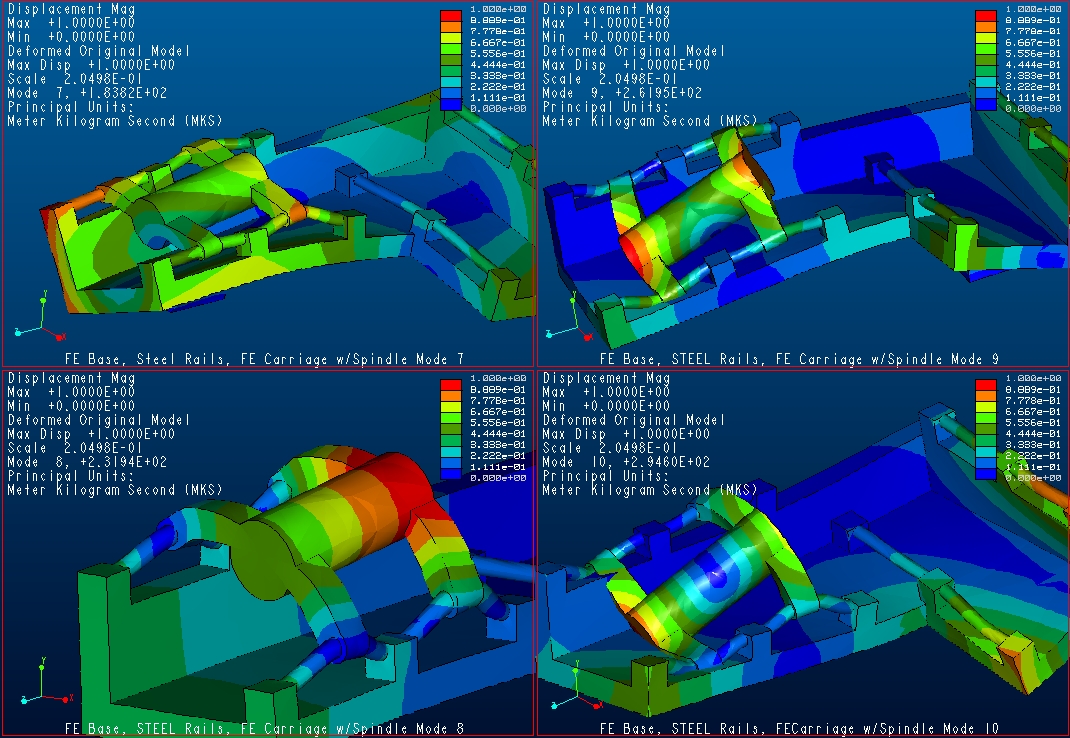
click on image to zoom in
Modes 7 through 10 (the first 4 non-solid body modes) of an aproximate base and carriage. The base walls are 4" thick Cast Iron, the Rails are 2" Diameter Steel, and the Carriage is Cast Iron. The is a model of the empty carriage. The solid cylinder is to simulate the spindle motor and work piece. There is also NO ballscrew and tail assembly in this model to drive the carriage in and out. This model was only done with one carriage to make a comparison with teh base without a carriage installed. The dimension of the components are aproximately the correct sizes.
| Mode | Frequency |
| 7 | 183 Hz |
| 8 | 231 Hz |
| 9 | 262 Hz |
| 10 | 294 Hz |

click on the image to zoom in
This model is the same as the one above but the carriage has been hollowed out to simulate the carriage WITHOUT the spindle motor and drive mechanism in it.
| Mode | Frequency |
| 7 | 181 Hz |
| 8 | 265 Hz |
| 9 | 270 Hz |
| 10 | 307 Hz |
For comparison the same Cast Iron base (without rails and carriage) was analysized. The results are below.
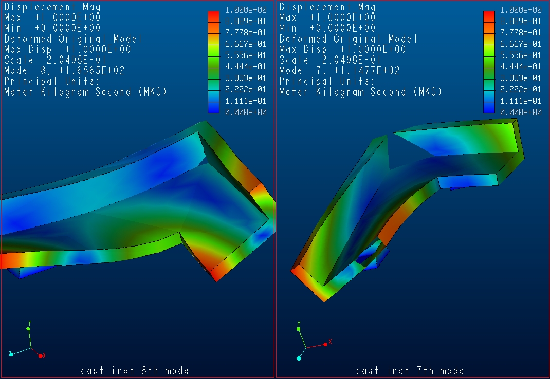
click on the image to zoom in
The 7th and 8th modes are the first two non-solid body modes of the base. Again the base is a models as solid 4" thick cast iron. We can see the dramatic increase in the resonant frequencies.
| Mode | Frequency | Change from w/ Carriage |
| 7 | 115 Hz | 66 Hz Lower |
| 8 | 165 Hz | 100 Hz Lower |
(Origenally POSTED ON 31 JAN 01)
Several other mounting configurations were considered:
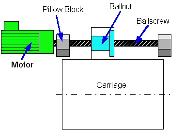 |
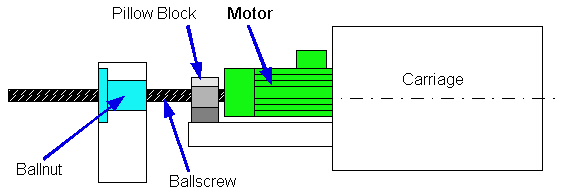
In this configuration the ballscrew and motors are mounted about the upper
set of rails for each carriage. Advantages:
Disadvantage:
|
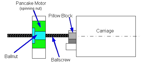 |
In this configuration a pancake motor spins the ballnut which drives the
screw/carriage in and out. Advantages:
Disadvantage:
|
 |
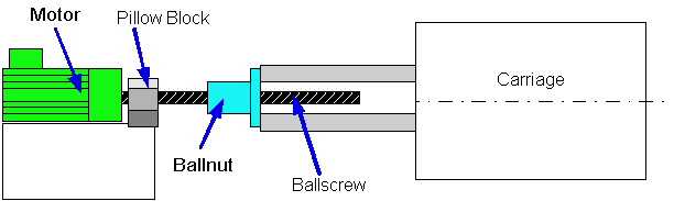
In this configuration a traditional servo motor is mounted on the
centerline of the carriage and spins the scew against a fixed ball nut. Advantages:
Disadvantage:
|
 |
THIS IS THE ONE USED In this configuration a traditional servo motor is mounted to the base on the centerline of the carriage Advantages:
Disadvantage:
|
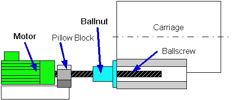 |
same as above but the motor/scew is offset slightly from the centerline to
allow the length of the carriage and base to be shortened dramatically on that leg. THIS OPTION COULD BE USED ON THE X AXIS (grinding carriage) |
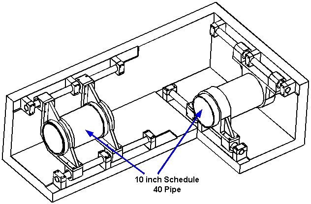
In an attempt the simply the casting need to build this machine the two carriages can be made of schedule 40 steel pipe, or a Aluminum Oxide tube. Here is a close up view of the grinder and workpiece carriage castings.
I also have done a quick check on the rail deflection under the weight of the carriage and workpiece. Here are the results.
Here are some calculations on the stiffness and thermal errors in a ballscrew. These errors are between 10 and 14 microns, and UNDETECTABLE if the axis position is measured by a rotary encoder on the ballscrew.
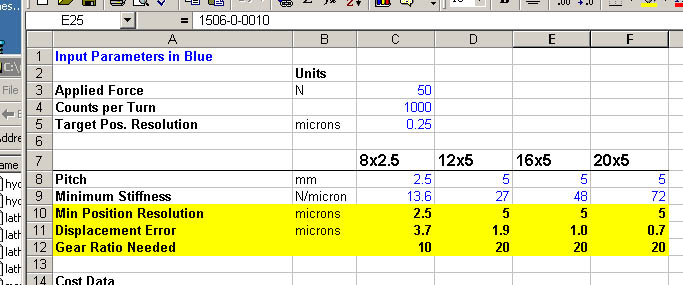
Here is a screen dump of the comparison of the four likely ballscrew sizes that we would use. The minimum stiffness values are from the star linear catalog (and ebbie's ballscrew selector spreadsheet), when the nut is at the midpoint of its travel.
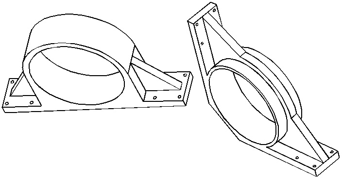
Bushing Mounting Concepts READ THIS ALEX (posted 10 DEC 00)
Some sketches of concepts for mounting the hydrobushing rails and the identical carriages for both spindles (posted 10 DEC 00)
Sketches of an improved core-less linear motor axtrusion design. For the Dry version of the Ceramic Samurai (posted 9 DEC 00)
The following concepts are currently undergoing error analysis. The errors of the Grinder Spindle of Concept 1 are used as the reference for comparing the errors of the other concepts. The values in the table below are the Error Reduction Factors for each concepts. The Error Reduction Factor (ERF) is the Magnitude of the Reference Error divided by the concept error. Larger ERFs imply smaller errors.
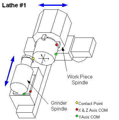 |
The Error Reduction Factors for Lathe #1's Grinder are all equal to 1 because Lathe #1's Grinder is the reference model. |
||||||||||||||||||||
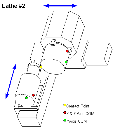 |
The spindle configurations for Lathes #1 and #2 are the same, so their error reduction factors are the same.
The only difference between Lathes #1 and #2 is in the height of the way which lathe #2's grinder travels on. Lathe #2's grinder way is higher than Lathe #1's. This shortens the distance between the grinder's COM and the Contact Point in Lathe #2. We see the expected reduction in error. |
||||||||||||||||||||||||||||||||||||||||
 |
|
||||||||||||||||||||||||||||||||||||||||
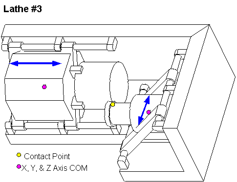
Lathe #3 is designed to bring the Center of Motion (COM) for both the grinder and work piece spindles as close to the contact point as possible to minimize the Abbe errors due to motions about this point.
Design Advantages:
Design Disadvantages:
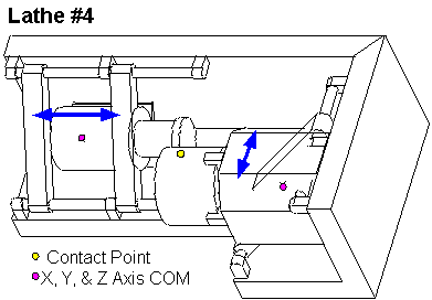 |
Lathe #4 is designed to take the advantages of Lathe #3 design, and improve the operator access to the work piece. A disadvantage of Lathe #4 is that since the grinder spindle is moving parallel to its rotational axis a "dressing" station for the grinding wheel is more difficult to add. |
||||||||||||||||||||||||||||||||||||||||
The purpose of this section is to compare the early machine concepts to determine which offers the least Abbe error. This design will be the easiest to meet the target accuracy. The machine is divided up into modules. The different methods of implementing each module is analyzed to see which will produce the least errors.
THIS IS NEW
This document shows some more sketch models of different concepts for moving the the spindle and tool. Is also shows the relative magnitude of the displacement errors cause by rotational motion about the Center of Motion of each concept.
Second Generation Sketch Models Error Comparisons (PDF file)
Several of of the early machine concepts involve moving the spindle/work piece to form on of the machine's axes of motion. This analysis was to determine the amount that error could be reduced by having the spindle's Center of Motion (COM) inline with with spindle shaft (as opposed to on the bottom of the spindle housing, the mechanically more convenient place).
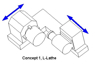
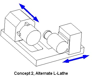
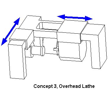
All of this concepts were sketched out with a grinding wheel. The logic being that if one can fit a grinding wheel on putting other tooling on is easy.
|
|
Concepts 1 and 2 assume the the main spindle can be small enough that it can be moved.
Concept 1 has the advantage that most of the ceramic swarf will not fall on any bearing surfaces.
Concept 2 has the advantage that the main spindle is travelling in a less critical direction.
|
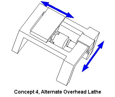
|
Concepts 3 and 4 have the advantage that the bearing surfaces/components are above the cutting area. This should make it easier to keep the bearing areas free of swarf. This will be especially important if contact motive and guide elements are used (ballscrews and ballrails).
The disadvantage is that operator access to the work piece is reduced and the machine structure must be very stiff since all the components are hanging from it.
|
|
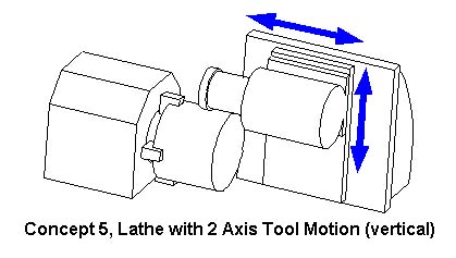
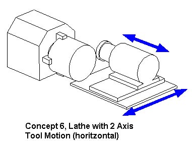
If it turns out that moving the main spindle is not feasible, then the tooling will have to be moved in both axis.
Concepts 5 has the advantage that the swarf is not falling on any bearing surfaces.