Back to the Main Ceramic Samurai
Here are some sketch models of concepts for being able to move the spindle/working and thereby using it as of the axis of the machine.
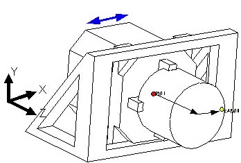
Here the spindle housing is supports on bearings underneath it. It could be designed to move in the X or Z directions (one or two axis).
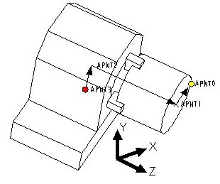
Here is a concepts that allows the spindle to move in the X direction. This has an advantage that the Center of Motion (COM) of the spindle housing in line with the spindle shaft. This greatly reduces the amount of Abbe error that the bearing can cause (compared to concept A, moving the spindle housing from the bottom of it). This has the added advantage that the bearing rails/surfaces and be mounted on the opposite side of the work piece. This will help prevent the ceramic swaf from of damaging the bearings. Spindle housing pitch does not produce and error at the cutting point but Yaw and Roll will.
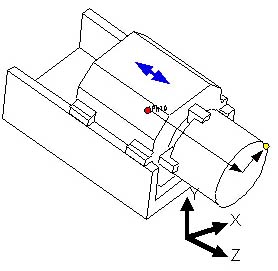
This concept also moves the COM of the spindle housing to inline with the spindle shaft (see Abbe Error Analysis for a comparison of the magiture with respect of Concept A). In this design the structure is simpler, but the bearing surfaces are more difficult to protect from the ceramic swaf. An advantage over Spindle Motion Concept B is that. Spindle Housing Roll does not produce an error at the cutting point. Carriage Yaw and Pitch do. Yaw and Pitch measurements are much easier to make over the range of motion. So this data can be easily collected and mapped into the controller. Being able to easily collect this data is important if contact element bearings are use. These bearing will have to be replaced, and the new bearing's errors remapped.