Back to Roger's Main Page
Back to Roger's Design Portfolio
Back to the Axtrusion Page
Back to the Ceramic Samurai Page
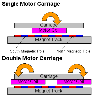
The Original Axtrusion used a permanent magnet linear motor to provide both the motive and preload forces. As the carriage passes over the alternating poles of the magnet track a moment is induced on it. This causes the carriage to pitch and yaw, limiting its application in ultra-high precision applications.
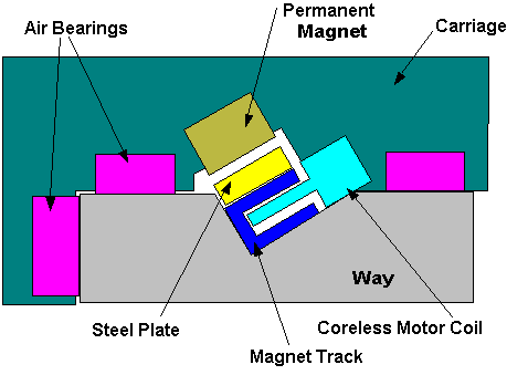
One solution to this pitch/yaw problem is to use a core-less linear motor, that will not induce as much of a torque on the carriage. Below is one possible configuration.

This design has a few problems.
The very high preload force between the permanent magnet and steel plate is transmitted though the U-shaped magnet track. This track may not be designed to be a load bearing member, and if it can handle the load its open cross section is not very stiff.
Assembly of this could be tricky, since the mounting holes are only on the bottom side of the U. The other option would be to glue the motor coil and steel to the way. This would not be very flexible.
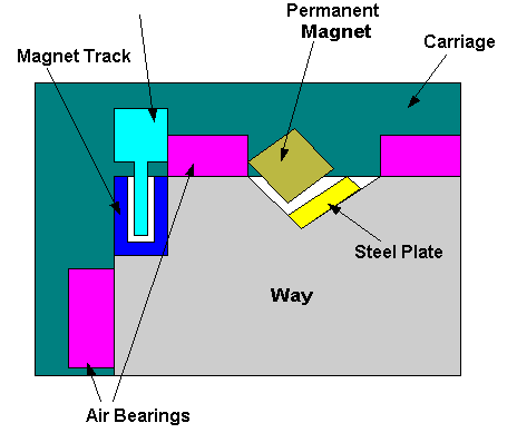
Another solution is put the core-less motor in a separate location from the preloading magnets.

This design has the following advantages:
Assembly is much easier.
The magnet track is not subjected to high forces.
The motive force is being applied very close to the center of stiffness axis for Yaw and Pitch. This will minimize errors to high accelerations.
The other option uses two motor coils on an single motor train, spaced apart by (n+1/2)*(magnet pitch) to produce two torque's that will cancel each other out. (Alex I know you already said this would not work, but this version has the torque's in OPPOSITE directions)
