Posted 10 DEC 00
It is important that we figure out how the Hydrobushing are going to be mounted. The fixed brushing is fairly straight forward. The free bushing (i.e. the one that can move slightly to allow for misalignment in the rails) is trickier. As I see it we have two options.

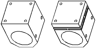
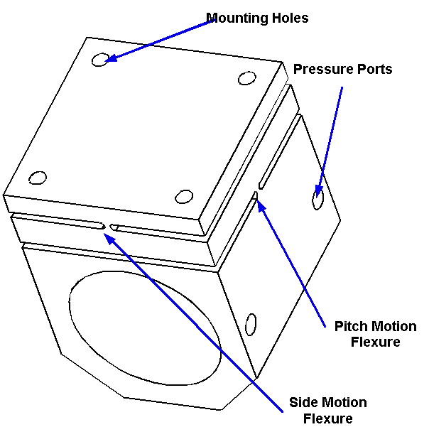
The four (4) holes on top are for mounting the Hydrobushing to the structure/carriage.
The two holes on the side are the pressure ports
The image on the left shows the fixed version and the image on the right shows its sister flexure based floating version.
These have been sized so that a 50mm ID 75mm OD and 100mm Long bushing could be inserted into the main cavity.
Can we get ride if the need to insert a separate bushing and just put the bushing features on the inside of the cavity directly, and injection mold the whole thing in one shot? That would make it smaller.
We could make the mounting hole patter match the patter for an equivalent linear rail truck.
If we do have to insert a separate bushing then we could make these mounts out of aluminum.

In the image above the side motion flexure has been move to above the pitch motion flexture and quite a bit farther from the bushing cavity. This will allow the side to side motion of the bushing to be more linear.
This is more complicated version. It will require more parts and more assembly, it has the possibility of wearing in the ceramic swarf environment. I think this option should only be persuded if the flexure based version will not work.