
The Flextester was a group project for Prof. Slocum Advanced Machine Design Class (2.75). Our group did the initial design work on the project. Since the semester ended several members of the group have continued the development of the Flextester. The patent on the Flextester includes all of us on it. This web site is based on the working site that we used as a group to present our work to our classmates and Prof. Slocum. It has been modified to make it a more self-contained presentation of the Flextester. I did most of the CAD work and FEA analysis (Pro/Engineer) for the initial prototype.
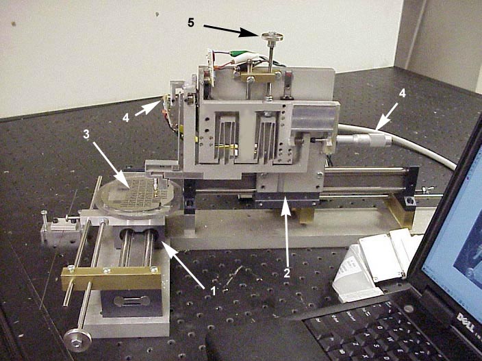
The photo of the flex tester above show some of its features. The precision stage is cut from a single sheet of aluminum. This a cheap way to give very precise and repeatable motion over small displacements. It uses optical sensors to measure both the displacement of the precision stage and the force being applied by the stage. The course X and Y stages are used to place the probe in the proper position on the wafer. The precision stage is then moved by means of a differential screw, and the force and displacement are measured and logged.
The Bistable Beam Structure
(As seen through a Microscope,
click on image for enlargement)
An excellent presentation that my teammate put together explaining the Flextester.(Point Point 3.5 meg)
| Roger "Pro-Engineer Master" Cortesi | rcortesi@mit.edu |
| Carolyn "Cryobabe" Phillips | thing@alum.mit.edu |
| Jin "MEMS Relay Master" Qiu | jqui@mit.edu |
| Joachim "Speed Typer" Sihler | sihler@mit.edu |
| Micah "Gonna Lose His Desk" Smith | smithmd@alum.mit.edu |
The Flextester is a measuring device which detects displacements and forces that occur in MEMS (micro-electro-mechanical systems). The initial focus is on a micro relays which consists of a bistable beam structure (see photo above). The bistability is used to flip the beam against an electrical contact i.e. turn the relays on and off. The problem is to measure the force that is necessary to flip the beam to the other side and to record the displacement. Calculations show that the theoretical maximum force is on the order of 100 mN and the displacement is on the order of 0.2 mm. In other words the Flextester is machine for measuring the stress strain curve of MEMS devices.
In the future, it might be possible to modify the design in order to apply the device to other MEMS as well.
The Initial Flextester Functional Requirements:Constraints:
- measure displacement (~0.2 mm)
- measure force (~100 mN)
- positioning wafer and probe relative to each other
- fixture so wafers can be repeatably placed inside the machine. Could part of the fixture be built into the wafer?
- adequate response time (~100 ms)
- probe has to fit into a small space (~0.2mm)
- economical / affordable
We took a field trip to the MIT MEMS lab to see how MEMs flexures are currently tested.
Next we had to select suitable components for build the Flextester.
Designing the Flexure
- Flexure Functional Requirements
- Initial Concept
- Concept version 0.7
- How Parallel does the motion need to be
- Final Concept
Selecting Displacement Sensors
A pair of optical position sensors an test amplification circuit on a bread board.
- Why Strain Gages won't work (write pages to link to)
- The Pro's & Con's of a Piezo (write pages to link to)
- Optical Excellence (the final solution) (write pages to link to)
Final Motive Method for Motion
- A Differential Screw
- A Transnational Flexure Drawing of Transnational flexure
- A Step Motor Driver
- A small precise amount of motion in the z-direction (a squatting flexure Drawing of squatting flexure)
- Producing a controlled displacement using
Ways to Measure, Generate, Transmit, Force and Displacement. (a list of Lego's and toys for accomplishing our objective)