
1. Investigates possibilities for Stage Purchase on the Web (sites found):
The stages that could be found on the web were too precise for our needs. We do not need a stage with 3 micron translational resolution. They also usually did not have the travel of 5" that we desire for our stage.
2. Build our own using two sliding pieces like Roger's thesis and an alumninum plate with holes and a Vacuum. Only XY stage will be required as Z movement will be incorporated into the flexure design. below is one possibility.
The desition to use a flexture to guide our probe arose from the following factors:
- The range of travel of the test probe is about 0.2 mm
- The test probe has to be lowered about 5 mm into the waffer for testing.
- The flextures can be easily cut from a few (or one) parts on the water jet cutter.
- Flexures are good at preventing motion in undesirable directions.

Design 1 (above): Thumbscrews turns flexure. Measure force with Piezo. Measure beam displacement of calibrated beam.
This design evolved by looking at other mems coordinate motion devices. Most of the designs that were found made use of some type of threaded rod to induce movement of a linear bearing system. These designs had a couple of "fat rabbits" that we tried to zone in on. First the use of a single threaded rod is limited by the number of threads that can be cut. A rod can be cut with a 120 threads/inch and get .008 inches of linear motion per turn, but is very expensive. A much simpler mechanism was used using a differential screw. This design utilized a screw with two very similar thread sizes. Each half of the thread could be run through two separate blocks, so that when the screw was turned one revolution only .001 inches of linear motion resulted. The calculations for linear motion for all the possible differential screws is shown on the screw spreadsheet. This design is further enhanced by the use of a stepper motor to turn the screw in incremental amounts. Using a modest stepper motor capable of rotating in 3.6 degree increments can attain a linear motion resolution of .3 microns! The second "fat rabbit" we identified was the use of linear bearings to attain the translational motion. Bearings are expensive and lead to problems with lubrication and friciton. It was postulated that by using a flexure device bearings could be eliminated and the device could be made out of one part. This also nicely mated into the design of using a differential screw, because the screw could be threaded into two separate members of the flexure to provide the linear motion. Foce would be measured by using a piezo-electric sensor mounted on the loading bar. Displacement would be inferred by counting revolution of the differential screw. The intial design above attembted to make the device simple and have the loading bar be of the same material as the linear flexure. This design had flaws several flaws. First the 3-D cuts would be very difficult to machine. Second, it did not deal with Abbey errors in the flexure. Third, it had no z or y stage of motion. Fourth, there were questions whether a Piezo could be used because of "discharge" issues. In general we had identified some interesing concepts, but the implementation needed refined. The final problem was that we were relying on the flexure and loading tip being extremely stiff by imposing the assumption that the displacement of the differential screw was the displacement of the mems relay.

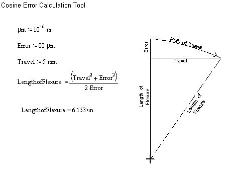
Design 2: Incorporating flexure z-axis movement. Used this design to create translational movement using a flesure device. Differential screw creates displacement. Calculations of cosine error. Did Pro-Engineer analysis of biflexure translational motion to design biflexure.
This design dealt with many of the implementation of issues of the previous design. The most obvious change was that a vertical stage was added using another flexural design actuated by a screw. The next change was that the single flexural elements were replaced with dual flexural elements. By placing dual flexures on both the horizontal and vertical stages straight line motion was insured. Secondly, by makinging each individual flexing element a "bi-flexure" the Abbe error was eliminated. To eliminate the stiffnes constraint of the flexure and the loading bar, optical sensor were included that sensed the displacement of both ends of the flexure. Along the same lines, a new mounting for the loading bar was developed which mounted the loading bar itself on a flexure. In this design the loading bar is made to be much stiffer than the "joint flexure" attaching it, so that all the deformation is in the joint flexure. Also by the use of a "magnified" loading bar with a short loading end and a long sensing end, small deflection of the tip would be amplified to the sensing end which could be detected by the optical elements. Force would be measured by calibrating the loading bar on a very accurate chemistry scale to produce a Force vs. Displacement curve. Thus once displacment of the tip is measured, force to deflect can be correlated. The loading bar is also detachable to account for different stiffness measurements. The problems with this design are that it requires mulitple parts to assemble. The double beam design requires that you bolt on plates on both sides that contain the double flexure because you want to keep the motino balanced on both sides. This design also does not allow for a space to house the stepper motor. The first thing we looked at in regards to the "bolting" problem was if the bi-flexures were necessary or could the cosine error be reduced by lengthening the members. It was shown in mathcad calculations that errors could be minimized if the flexures were made substantially long.

Design 3: Optical Sensors measure the displacement of the needle and the instrument while pushing biflexure beam. Compared to displacement of insturment with no load force. The translation in the z-axis and the y-axis assisted with stepper motors. A Differential Screw used to get 0.3 micron resolution translations from the instrument.
This design incorporates the idea of using long flexures to minimize the cosine errors. Now there is also room to insert the stepper drive motor. The design also incorporates a mounting device for the stepper motor that allow it to slide in and out as the motor turns using a dowel pin design. This major problem with design is that the necessary size of the flexures makes it very large and there are still small errors. It would be nice to go back to the bi-flexure design to totatlly eliminate cosine errors.
Design 4: Return to bi-flexures and tweaking of design.
This design solves many of the problems that have plagued the tester from the beginning. A new "super" bi-flexure has been used that allows linear motion with no error out of one piece. This allows for the tester to be more compact, accomodate the stepper motors, and avoid Abbey Errors. Other problems that were realized during this iteration and solved were the ability to drill and tap the holes, drill and attach the motors, and attach the loading bar. There were major problems with simply drilling and tapping the holes for the differential screw. First of all you would have to drill through the entire flexure, which raised major machining issues such as fixturing this awkward piece, drilling such a large hole, and finally tapping inside an awkward geometry. Also, if the holes could be drilled and tappped, how could the differential screw be inserted without pre-stressing the flexures. Initially design frustrations were alleviated by using brass inserts in the tester. This way the channel for the screw could be water-jetted. Then the screw could be threaded through the different threaded brass inserts and then finally inserted into the channel and bolted onto the tester through holes that could also be water-jetted.. The same holes used to secure the brass inserts could also be used to fixture the stepper motors to the tester. The loading bar problem was addressed and for a prototype it was decided that a simple bolting method would suffice to attach a steel bar that could be sharpened to a point. The bar will be waterjetted in order to get a flexure joint in it, and then finish ground on a grinder to get a point fine enough to insert into the relay. Future design and production models will apply a "sexier" kinematic mounting, but for now a groove will be milled in the teser that the loading bar will fit into. Two bolts through the "horshoe" will hold the loading bar in place. Parts of the design that still have to be worked on are the rough x-y stage for the tester.
Analysis:
Error Analysis of Abbe Errors of Translational Motion of Flexure:
Pro-Engineer Analysis of Load Effect on a Flexure Translational motion. This model was used as a staring point for estimating the size of the flextures needed to achive the desired stiffness. The displacement is 0.07 mm for an applied force of 0.1 Newtons. The flexture is cut from a 1/4 inch thick sheet of 6061-T6 Aluminum. The legs are 2mm wide and about 175 mm long.
