Back to Roger's Web Page
Back to Roger's Design Portfolio
I originally did these calculations as part of the Underwater Experiment Canister project. They are redoing (in an electronic form) some of the calculations done by By Arnold G. Sharp of the Woods Hole Oceanographic Institute in August 1981.
Our use for them was to figure out the feasibility of using off the shelf stainless steel pipe as a pressure vessel for C and D cell batteries. Pipe sizes came from the McMaster-Carr On-Line Catalog. Note that there is not much room with the batteries in the pipe for internal wiring so a larger pipe size might be needed. One could run water proof connector out both ends.
In the end for our project we ended up pressure compensating the D cell batters to allow them to be used to 10,000 psi in an oil bath. This required no heavy pressure housing. See the paper on How To Pressure Compensate Alkaline Batteries.
| Battery OD | Closest Standard Pipe Size |
Pipe ID | Wall Thickness | T/ID ratio |
Estimated Crush Depth (no safety margin) |
|
| D Cell | 1.346 in / 34.2 mm | 1 1/4" Sched 40 | 1.380 in /35.1 mm | 0.140 in / 3.56 mm | 0.101 | 3800 m (yielding) |
| C Cell | 1.031 in / 26.2 mm | 1" Sched 40 | 1.049 in / 26.6 mm | 0.133 in / 3.38 mm | 0.127 | 4600 m (yielding) |
| Required T/ID of SS endcap |
Required Thickness of Stainless Steel End Cap |
Required T/ID Epoxy End Cap |
Required Thickness of Epoxy End Cap |
|
| D Cell | 0.223 | 0.31 in / 7.8 mm | 0.482 | 0.665 in / 16.9 mm |
| C Cell | 0.262 | 0.28 in / 7.0 mm | 0.531 | 0.557 in / 14.1 mm |
The T/ID ratio and thickness for the epoxy is very crude guess because clearly the edges of the epoxy are not simply supported. But this value is useful as an approximation of how much potting would be needed to prevent an end that was only potted from yielding. There may be considerable variation in the values for the material properties of the epoxy. The values used for this calculation were from the West Marine web page and are E = 0.38 GPa, Y= 50 MPa, and Poisson's Ratio of 0.33.
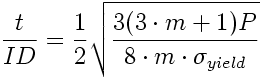
To calculate the required thickness to unsupported ID for a simply supported endcap where P is pressure, m is 1/v (one over the poisson's ratio) and sigma_yield is the yield stress of the end cap material.
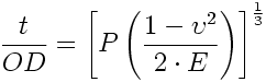
To calculate the required thickness to cylinder OD for a simple cylinder where P is external pressure, v is the poisson's ratio, and E is the young's modulus of cylinder.
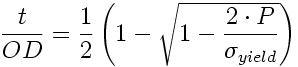
To calculate the required thickness to cylinder OD for a simple cylinder where P is pressure, v is the poisson's ratio, and sigma_yield is the yield stress of the cylinder material.
Woods Hole Oceanographic Institute Technical Memorandum 3-81
Failure Curves of Cylindrical/Spherical Pressure Vessels and Flat End Caps.
By Arnold G. Sharp, August 1981Roark's Formulas for Stress and Strain, 6th Edition
By Warren C. Young 1989 McGraw-HillMark's Standard Handbook for Mechanical Engineers, pp6-36
| The Excel file that generates the plots of Thickness/Diameter vs. Depth | Simple Pressure Vessel Failure Modes.xls |
| The Mathcad file that generates the plots of Thickness/Diameter vs. Depth | Simple Pressure Vessel Failure Modes.mcd |
| An Acrobat PDF file of the Mathcad file with plots for stainless steel 302/304/316. | Simple Pressure Vessel Failure Modes.pdf |
The image below shows an example of the plots and equations for both the cylinder and end cap with the material properties of Stainless Steel 302/304/316.
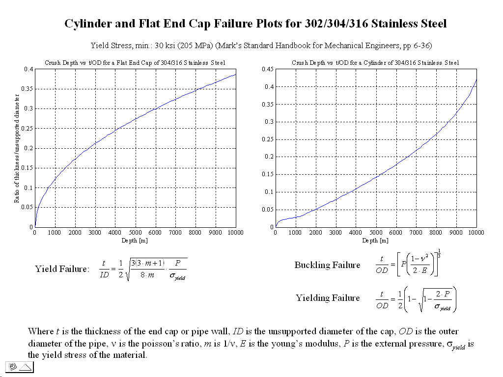
The user enters the material's properties (Young's Modulus, Yield Stress, and Poisson's Ratio) and the files return plots of Thickness/Diameter ratio vs. Depth. By returning a value for the Thickness/Diameter ratio any size cylinder or end cap can be evaluated. Note: for Cylinders the Outer Diameter is used and for the end cap the Inner Diameter is used.
To prevent failure the Thickness/Diameter ratio should be thicker than those specified by the curves There is NO safety margin in the curves. These results also do not take into account the surface defects which could cause failure sooner.
The original Woods Hole document does not give the equations so I had to re-derive them from those listed in Roark and Young. The equations that I derived do produce plots that match those in the original Woods Hole document. However as I write this I cannot find which equation I used as the starting point for the buckling of the thick-walled cylinder.
The starting point for the thick-walled cylinder failure by yielding is Roark, pp. 638 Table 32 "Formula's for thick walled pressure vessel" Case 1c
The starting point for the yielding of a simply supported end cap is Roark pp. 428 Table 24 "Formulas for flat circular plates of constant thickness" Case 10a
Note: that the end cap is modeled as simply supported. This means its edge is supporting no moment (i.e. it is just resting on end of the pipe. To model an end cap with clamped edges use the equation in Roark pp. 428 Table 24 "Formulas for flat circular plates of constant thickness" Case 10 b. I have not done this derivation to return T/ID as a function of pressure.