Back to Roger's Main Page
Back to Roger's Design Portfolio
By Roger Cortesi, SM Mechanical Engineering, MIT 13 November 1999
The MITESS (Moored In-situ Trace Element Serial Sampler) tests these compensated alkaline batteries at 5 depths from 200 meters to 3400 meters.
Alkaline cells are very cheap, readily available, and have a very high power density. A method of compensating allows deep ocean use without the limitations (in maximum depth, weight, and safety) of putting them in a pressure vessel.
Duracell™ brand alkaline batteries operate at high ambient pressures if the internal void spaces of the battery are filled. The technique of filling the void spaces with either oil or epoxy has been tested on C and D sized cells up to a pressure of 10,000 psi. This is a cheap non-rechargeable power supply with more than twice the energy density of lead acid batteries. We have applied this technique to deep ocean instrumentation. The capacity of the alkaline batteries matched the manufacturer's specifications after being modified and tested to a pressure of 10,000 psi. In two cases the modification was improperly applied. These cells were deformed by the high ambient pressure. In these cases only a slight reduction in capacity was observed.
The modification for a high-pressure environment takes less then 5 minutes per cell. Skilled operators can perform it in 2 minutes per cell. Everready™ brand batteries were also tested and found unsuitable for this modification due to differences in their internal construction.
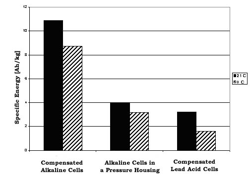
Figure 1: SPECIFIC ENERGY [Ah/kg] vs. CELL TYPE AT 0° C and 21° C. The data for this plot comes from the manufacture's specifications. For a nominal 12-volt battery pack, 10 D cell batteries in series are required. Duracell™ lists a nominal capacity of 15Ah for each D. The sealed lead-acid cell is a 12 volt 17Ah cell (made by Panasonic™ or Powersonic™). The compensated alkaline cells use the technique described in this paper. The alkaline cells in a pressure housing include the mass of a 1-1/4” stainless steel pipe and end caps.
The following points should be kept in mind using the chart above: The D Cell pack in a stainless steel pressure vessel can only be used to a depth of 6,800 feet (3,000 psi) before the safety factor of 1.5 on the failure of vessel walls is violated. The compensated alkaline and lead acid batteries have been tested to 10,000 psi. To achieve the rated capacity on the alkaline cells, each cell must be discharged to 0.8 volts. In the deep ocean the packs will be at a temperature near 0°C (32°F). This will reduce the capacity of the alkaline batteries to approximately 80% of their nominal capacity, and lead acid cells to 50%. The loss in capacity is also dependent on discharge rate so check the manufacturer's literature for your particular loading scenario. Figure 1 uses the specs for discharging through a 2.2 Ohm resistance.
An alkaline battery has two void spaces. These must be filled if the battery is to operate at high ambient pressures. One is in the nipple on the positive end. The other is in the end section at the negative terminal (see white arrows in figure 2). This compensation technique has been successfully applied to Duracellä brand D and C sized alkaline batteries. An attempt was made at using this technique on D cell Everreadyä brand batteries; however, the internal construction of the battery did not make this possible. Fluid would immediately leak from the negative void of the Everreadyä battery when they were drilled.

Figure 2: THE INTERNAL CONSTRUCTION OF A DURACELL ALKALINE BATTERY. The two white arrows indicate the void spaces that must be filled to prevent the cell from being crushed by high ambient pressures.
First, a hole is drilled in the nipple on the positive cap of the battery. This is a trivial operation. Care should be taken to drill only through the nipple and not into the actual battery.
WARNING!!! DRILLING INTO A BATTERY CAN BE DANGEROUS IF CARE IS NOT TAKEN. The holes should be drilled with a drill press using the depth stop to prevent over drilling into the anode. The battery should be held in a fixture, NOT BY HAND. See Appendix A for a possible fixture design. Do not run the drill longer than needed in the battery to prevent heat build up in the cell. And, of course, safety goggles or a face shield should be worn.
Second, holes are drilled in the negative cap of the battery. This operation requires that 1/8-inch holes be started at each point where a through hole is desired. See figure 3 for a good approximate location. DO NOT drill all the way through to the void space around the plastic grommet. Drill until the outer layer of metal (negative cap) is cleared from the cardboard insulator underneath it. DO NOT drill though the insulator with the 1/8" drill.
When 1/8-inch hole is complete, clear the burrs from it.A very small drill, number 60 or 59, is used to drill through the cardboard insulator and the positive terminal underneath. Do not drill through the plastic cap under the positive terimal.This will expose the gel in the cell. The smaller drill size and burr clearing is needed to prevent the terminals from being short circuited by either the drill bit or burrs. Again the use of a depth stop is recommended to prevent over drilling into the anode.
Testing these modified batteries at Woods Hole has revealed that more than one hole is needed in the negative end of the battery. If only one hole is present, the end cap will be deformed under the cycling pressure. Two or three holes, equally spaced around the axis is recommended.
The compensation material can either be oil or epoxy. Both materials have been tested. The epoxy seems to be the safer option of the two. In the event that there is some end cap deformation, the epoxy will help prevent the positive and negative terminals from piercing the cardboard insulator and short circuiting the battery. Epoxy also insures that none of the fluids inside the battery leak out through the holes. The epoxy is injected into the void space at the negative end with a syringe until it flows out of the other holes. More epoxy is injected a few minutes later when the initial epoxy settles.
The epoxy used in all the epoxy compensated cells was West Systems marine epoxy (105 resin and 205 slow hardener). If the battery is used in an oil compensated environment then only the void space in the negative end of the battery needs to be filled with epoxy. If the battery is to be immersed in seawater then both void spaces should be filled with epoxy, waterproof leads soldered on, and then the whole battery potted in epoxy. The epoxy manufacturer's instructions on applying more epoxy to an already cured epoxy layer should be followed.
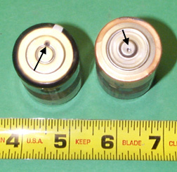
Figure 3: A PAIR OF COMPENSATED D CELL BATTERIES. Notice the holes drilled to prevent implosion of their void spaces (arrows). Unlike the left battery shown here, more than one hole is needed in the negative end of the battery (left) to ensure a complete filling of the negative void space.
The modified battery tests were completed at the Woods Hole Oceanographic Institute (WHOI), Electric Boat Corporation (EB), and aboard Submarine NR-1 (US Navy Submarine Group 2, Groton CT).
For the tests at Woods Holes, the cells were placed in sealed plastic bags filled with transformer oil. The bagging prevented contamination of the pressure chamber's working fluid (transformer oil) in the event that the cells leaked. Some cells were taken to 2,500 psi and others were taken to 10,000 psi. All cells were held at the maximum test pressure for 30 minutes.
After the batteries were tested at WHOI four of them (three D cells and one C cell) were discharged completely to test for any loss of capacity. Each battery was discharged through a 10 Ohm resistor and its voltage logged over time until it was discharged. This data was plotted and compared with Duracell's specifications (see figure 4 for D cell data). The only significant loss of capacity seems to be in the two batteries that only had some deformation in the negative ends. These two batteries only had one hole drilled in their negative ends
A test at EB was done to verify that instrument package was safe to send to sea aboard NR-1. The instrument housing was filled with mineral oil to eliminate any implodable volumes within it. The epoxy compensated batteries and the circuits they were powering (a data logger) were placed in the mineral oil. The test cycled the system from atmospheric pressure to 2,000 psi ten (10) times. The final cycle was held for an hour at 2,000 psi. The data logger functioned throughout the test.
The test on Submarine NR-1 was a ten day deployment in May of 1999 where the ship obtained a maximum depth of 2980 feet (1300 psi). The same two batteries that powered the data logger in the EB test were used to power the same logger here. The batteries functioned well during all of their tests.
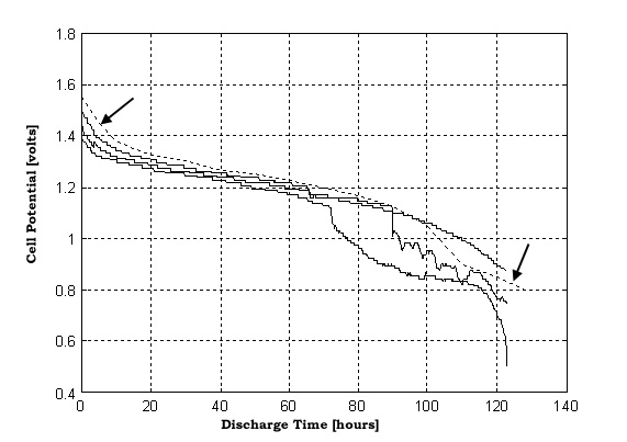
Figure 4: VOLTAGE VS. TIME CURVES FOR THREE COMPENSATED D CELL BATTERIES. The cells were discharging through a 10 ohm resistor after they have been subjected to 10,000 psi. The dashed line (marked by arrows) is Duracell’s ™ specified discharge curve for a D cell battery, through a 10 ohm resistor, at room temperature. The two of the batteries show a significant drop in voltage between 70 and 90 hours. These were both batteries that had only one hole drilled in their negative end. Their negative end plates experienced significant deformation. Even with this, very little capacity seems to have been lost.
I would particularly like to thank the following people for all there help and advise with this project.
CAPT Dennis Mahoney, USN of the MIT Naval Engineering and Construction Program provided funding for this project. Dr. Jim Bales (MIT Edgerton Center, formerly of MIT Sea Grant), and Dr. Allen Bradley (WHOI) were also an enormous help in providing technical advise. Midshipman Nicole Justis USNR, Midshipman Melissa Harness, USNR, and Midshipman Kevin Fergison USNR of the MIT NROTC project we also a big help in performing this study. Allen Ruditzy of Electric Boat Corporation's NR-1 Project Office and the CDR Chaz Richards, USN (OIC of Submarine NR-1) and LT Doug Perry, USN (XO Submarine NR-1) for all of their fantastic help in working with NR-1. And last but not least Karlin Wunnup of the WHOI who taught us how to use the pressure vessel and put up with all of our questions and mess.
Woods Hole Oceanographic Institute Technical Memorandum 3-81, by Arnold G. Sharp, August 1981. Failure Curves of Cylindrical/Spherical Pressure Vessels and Flat End Caps.
http://www.duracell.com/ The Duracell web site. Lots of detailed information and specifications on their products (including Alkaline batteries).http://www.westsystem.com/ The epoxy used in the compensating the batteries. The physical properties for the different types of epoxy are listed..
http://www.westsystem.com/ The epoxy used in the compensating the batteries. The physical properties for the different types of epoxy are listed..
http://www.power-sonic.com/ A manufacture of sealed lead acid batteries. Specifications for all their battery products are listed on-line.