By Roger Cortesi of the MIT Precision Engineering Research Group
This is an example of some notes and collaboration on designing a machine tool. It is not intended to be a finished presentation of the project.
Theses note were not publicly viewable until early 2004.
The power point file for my intial thoughts on an Axtrusion based lathe for 2.75 students. (2.1 Megs in size).
Alex download this final draft of the power point file for Hardinge and let me know what you think.
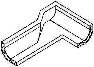
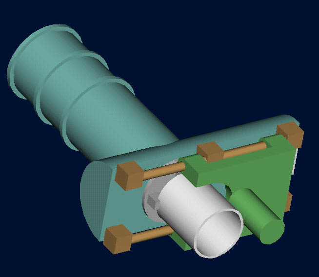
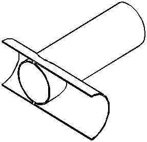
The pipe lathe concepts. The carriages still need some work, but the the COM of the tool carriage (green) is at the center of the grinding wheel. So errors in roll, pitch, and yaw of the tool carriage should have minimal effect on the part accuracy. The work piece carriage/spindle assembly (gray) has a hydrostatic bearing on its outside surface, and runs on the inside of the worpiece pipe. Click to enlarge.
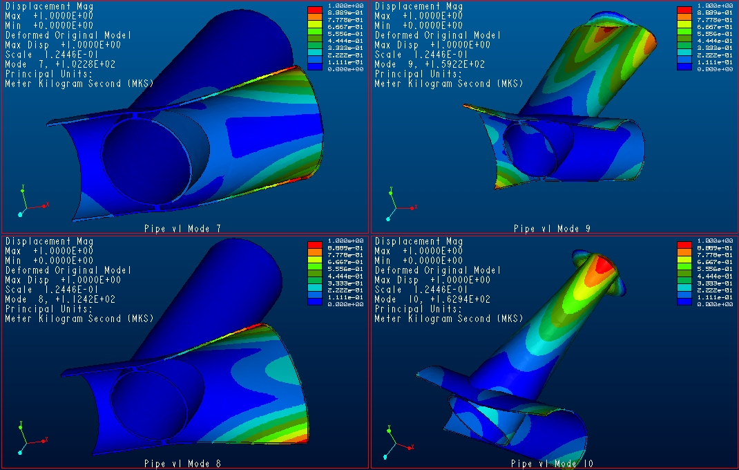
Yesterday I was having trouble getting the modal analysis of the pipe lathe with stiffer support plates to run. The FEA would stop in the second pass without any error messages. So today I removed the support plates, and I kept the end caps on the tool half-pipe and stiffening rings around the workpiece pipe. The results are awesome.
| Weight | 246 kg |
| Mode 7 | 244 Hz |
| Mode 8 | 321 Hz |
| Mode 9 | 325 Hz |
| Mode 10 | 425 Hz |
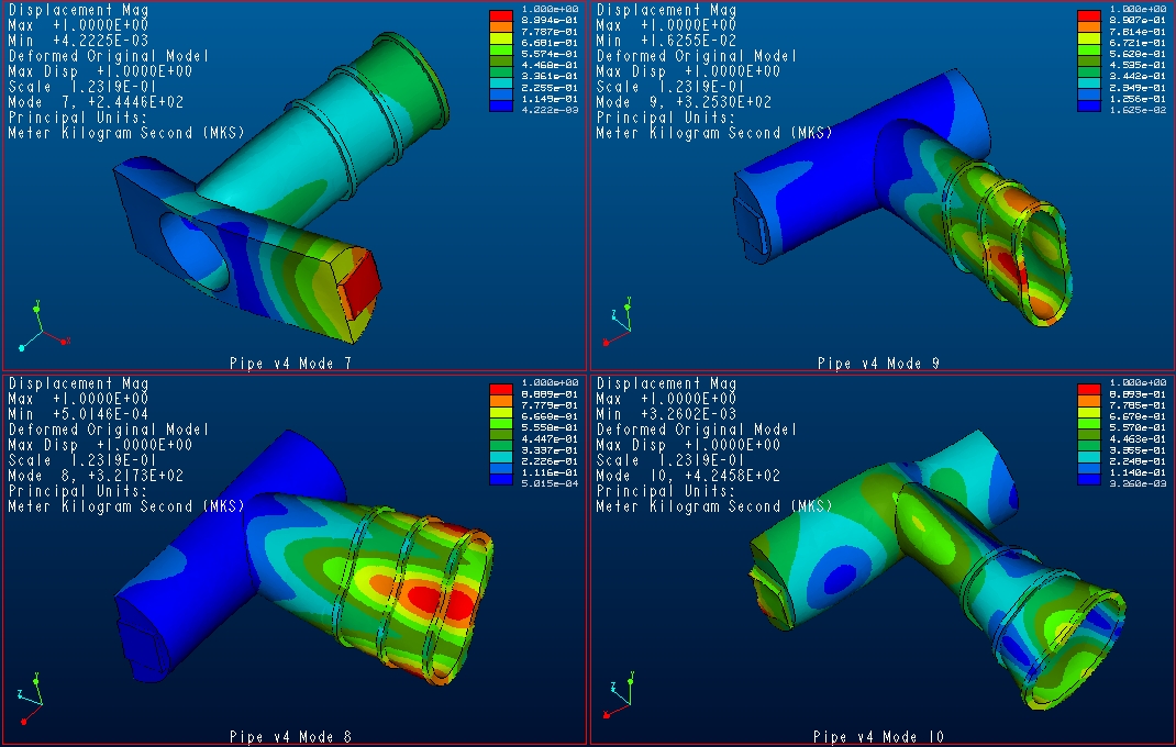
Stiffer Pipe Lathe Modes 7 through 10. Click to enlarge.
See yesterday's entry for the development path that lead to this version of the pipe lathe.
Ok today I got a lot done. After doing modal analysis on a lot of variants on the L concept I have moved away from it because I have a lot of trouble getting Mode 7 (the first no solid body mode to be greater than about 120 Hz). After consulting with Alex we agreed that 150 Hz was the minimum and greater than 200 Hz was preferred for mode 7. Below is a table with typical examples of the L concept that I analysis. These L bases are also very heavy.
|
|
|
| Weight: 896 kg, Mode 7: 79 Hz | Weight: 1200 kg, Mode 7: 92 Hz | Weight: 928 kg, Mode 7: 84 Hz |
|
|
All these analysis were modeled in cast iron |
| Weight: 881 kg, Mode 7: 70 Hz | Weight: 928 kg, Mode 7: 129 Hz |
I was having trouble getting the frequencies as high as I would like with the L configuration. So I started analyzing another configuration I thought of earlier. It is the pipe lathe.


This concept could be made from readily available steel pipe, epoxied together (to prevent imparting thermal stresses into the structure which would come from welding). The workpiece carriage slides inside the workpiece pipe. The grinding wheel moves back and forth on the grinding pipe (or half pipe). This configuration allows the grinding wheel to be at the center of motion (COM) for the tool axis in both pitch and roll. This is good because roll errors are much more difficult to map.
First I did some modal analysis of the pipe concept to see if the results were good enough to pursue the idea.
I based the structure on 16" OD workpiece pipe and an 18" OD tool half pipe. Both pipes have a wall thickness of 3/8". The pipes are steel.
At first glance these frequencies don't appear to be much higher than the L concepts, but the base is 1/10 the weight. Looking at the actual shapes of the modes, it is apparent that it fairly easy to stiffness the workpiece and tool pipes.
 |
Weight | 166 kg |
Pipe version 1, Modes 7 through 10. Click to enlarge. |
| Mode 7 | 102 Hz | ||
| Mode 8 | 112 Hz | ||
| Mode 9 | 159 Hz | ||
| Mode 10 | 163 Hz | ||
This version has problems with the analysis, so it is not presented here.
A 1/2 inch plate was put on the front face of the half pipe, and support plates were added because they would have the added effect of stiffening the structure. The modal image below shows that Mode 7, 8, and 9 are due to flimsy support elements. The first mode with major structural deflection is not until 342 Hz!!!
 |
Weight | 283 kg | 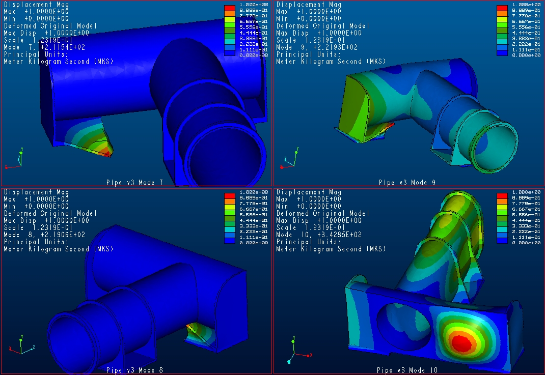 Pipe Lathe version 2, Modes 7 through 10. Click to enlarge. |
| Mode 7 | 211 Hz | ||
| Mode 8 | 219 Hz | ||
| Mode 9 | 222 Hz | ||
| Mode 10 | 342 Hz | ||
Here is an isometric view of a simpler version of the alternate L Base (both w/ and w/o fillets). This version allows the tool axis to be in the center of the tool carriage and be collinear with the workpiece axis (i.e. driven all the way in).
|
|
Alternate
L Base without Fillets |
Alternate
L Base with Fillets |
| Alternate L Base | Alternate L Base w/ fillets | |
| Weight | 2095 kg | 2238 kg |
| Mode 7 | 115 Hz | 126 Hz |
| Mode 8 | 175 Hz | 197 Hz |
| Mode 9 | 247 Hz | 272 Hz |
| Mode 10 | 283 Hz | 315 Hz |
Ok I just had an idea for keeping the corners of the L connected and allowing the grinding wheel to be at the center of motion its carriage: a "skewed L" design.
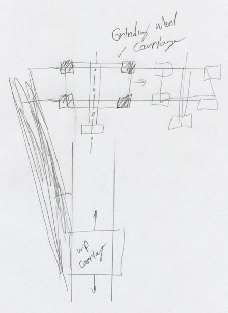
The long leg of the L is at an angel from the workpiece rails. This allows the grinding wheel carriage to travel all the way to the center of the workpiece.
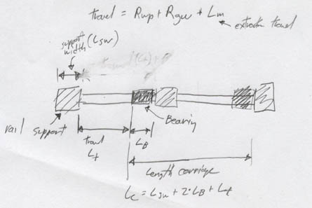
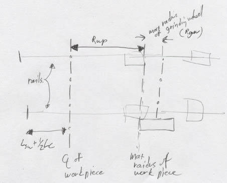
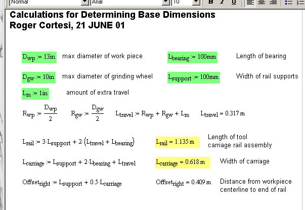
The above sketches and calculation allow me to compute the length of the tool carriage, rails and amount of offset to all the grinding wheel to reach the maximum diameter of the workpiece, a margin for error and all the tool axis to be brought collinear with the workpiece carriage.
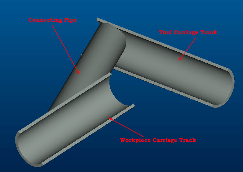
Ok this sketch is not as elegant as I would like it, but I'm out of time for the day. The connecting pipe will provide a lot of tortional stiffness to keep the workpiece carriage track from pitching. This may not be the best implementation of this modified L concept, but you get the idea.
I'm going to get a scanner in a couple days and then it will be much easier for me to post concept sketches.
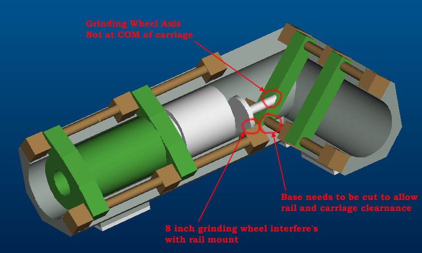
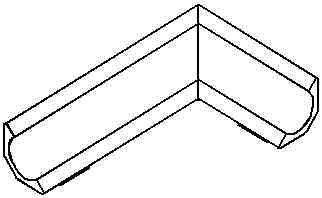
This shows the interference's with between the base, rails, and tool carriage. The problem here is that the axis of the grinding wheel must be all the way at the forward end of the tool carriage to be able to reach the center of the workpiece. This may not be a big problem because the grinding wheel moving up and down is in a non-sensitive direction. The work piece shown is 12 inches long and 12 inches in diameter.
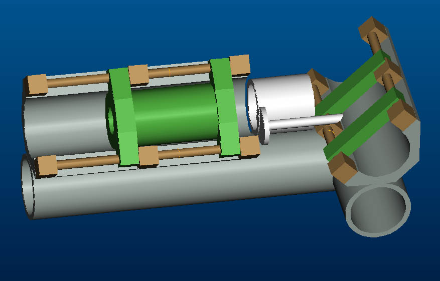
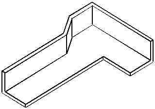
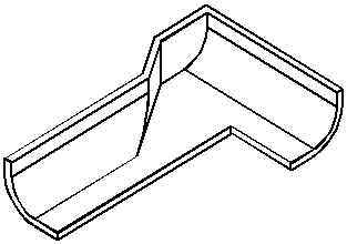
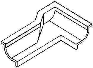
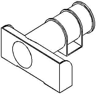
This shows a concept for allowing the axis of the grinding wheel to be moved back to the Center of Motion of the tool carriage. The two sides of the original L are split apart and mounted on a base. I have sketched in a base made of 14 inch pipe here but there could be several other possible configuration. The main advantage of this design it is much easier to resolve the interference problems and to easily scale the size of the machine to fit the customer's workpiece size. The disadvantages are a more expensive and heavier base. But the quality of the base can be determined by the customer's budget/quality requirements. The C shaped pieces could be annozied extruded aluminum.
Ok I have finished up the base only modal analysis for the C shaped base only (i.e. no carriage or rails). The base is approximately the same size as the Double L design posted earlier. I ran the analysis for the base made of three different materials (Cast Iron 40, 6061 Aluminum, and Nylon)
| Cast Iron "C" Base Only | 6061 Aluminum "C" Base Only | Nylon "C" Base Only | |
|---|---|---|---|
| Base Weight | 643 kg | 238 kg | 102 kg |
| Mode 7 | 100 Hz | 118 Hz | 42 Hz |
| Mode 8 | 150 Hz | 180 Hz | 65 Hz |
| Mode 9 | 228 Hz | 272 Hz | 97 Hz |
| Mode 10 | 284 Hz | 340 Hz | 121 Hz |
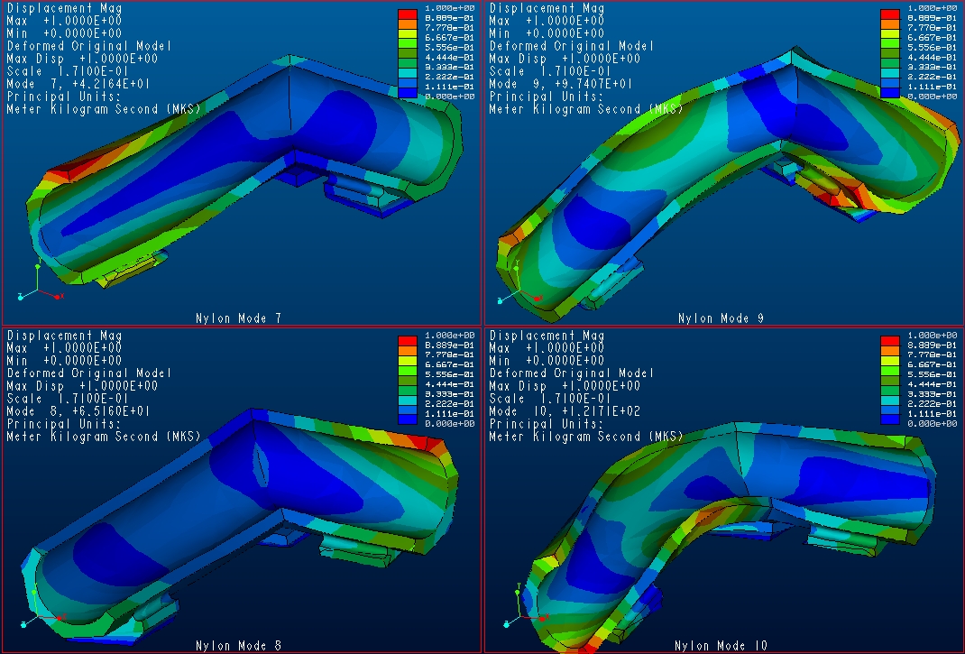
Modes of for the Nylon C Base
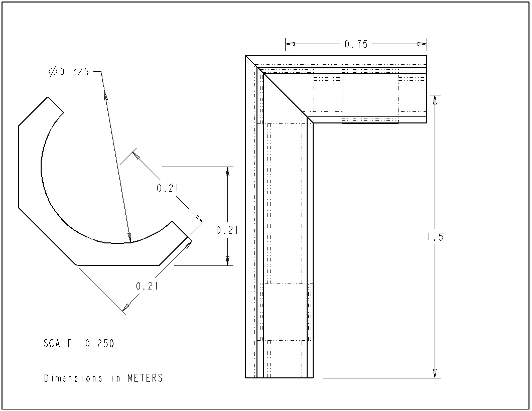
Overall Dimensions of the "C" Base
The modal analysis still in progress. After chasing down several inconsistencies in the model I'm finally getting consistent results. Mode 7 through 10 are being compared for various base, rail, and carriage variations (Modes 1 through 6 are the solid body translation and rotation modes, and are not significant).
The table below shows the results from three sets of analysis. All using a solid cast iron base. The values in () are for the difference between that value and analysis with no carriage. We can see that if aluminum oxide rails are used then adding the work piece carriage DOES NOT significantly lower the natural modes. It actually may increase them slightly.
| Mode | Solid Cast Iron (40) Base No Rails, No Carriage |
Solid Cast Iron (40) Base Steel Rails Cast Iron (40) Work Piece Carriage |
Solid Cast Iron (40) Base Aluminum Oxide Rails Cast Iron (40) Work Piece Carriage |
| 7 | 113 Hz | 106 Hz (-7 Hz) | 113 (0 Hz) |
| 8 | 154 Hz | 159 Hz (+4 Hz) | 167 (+13 Hz) |
| 9 | 260 Hz | 247 Hz (-13 Hz) | 280 (+20 Hz) |
| 10 | 304 Hz | 270 Hz (-34 Hz) | 310 (+6 Hz) |
END Material Posted on 14 JUNE
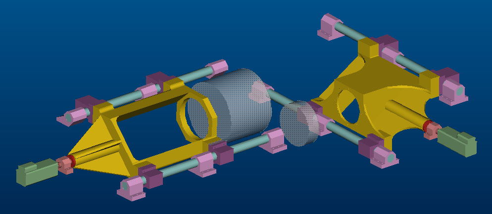
Ok here is the latest concepts for the work piece and grinder carriages. The spindles that fit into each carriage are not shown. These carriages are sized to hold a 10"dia by 24" long work piece spindle (left carriage), and a 8" dia by 16" long grinding wheel spindle. That 16" inches is the maximum space available INSIDE the carriage. The grinding wheel is offset set from the carriage by 13" so the maximum length from grinding wheel spindle from wheel to tail is 29".
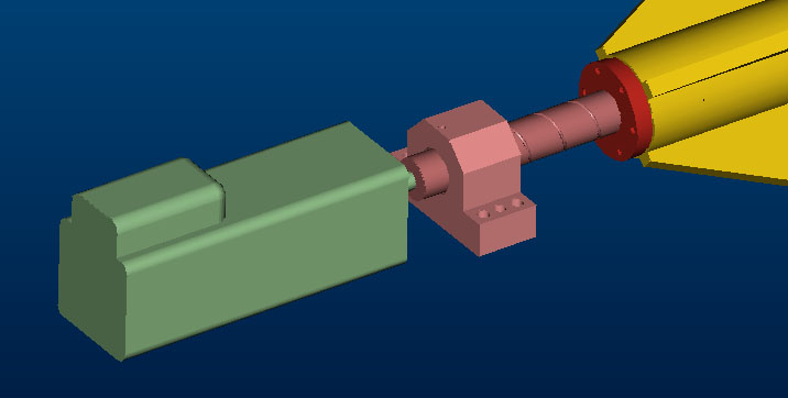
Here is a close up of the motor, pillow block, ballscrew, ballnut, carriage assembly.
More information was posted on 31 Jan 01, but it has been move to the site archive
END MATERIAL POSTED ON 31 JAN 01
This is where outdated information from the web site is stored. This it is to keep a record of what was thought of, tried, calculated etc. in the process of designing the Ceramic Samurai.