 |
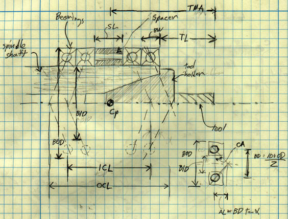
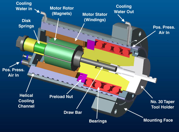
| Figure 1: Major Mini-Spindle components and layout. |
Note: This write-up does not include the latest design integrations of the spindle.
|
| Figure 1: Major Mini-Spindle components and layout. |
This spindle has several features that allow it to achieve high accuracy at low cost.
Our designed maximum spindle speed for the prototype and low cost versions of the Mini-Mill is 12,000 RPM.
A stock frameless motor is mounted directly on the shaft and into the spindle housing. This eliminates the cost and weight of a separate motor housing. By mounting the motor on the shaft the bulk needed to mount the motor on one side is eliminated. The disadvantage of this configuration, is the motor must be capable of achieving the maximum spindle speed. If it was mounted on one side, and a belt and pulley used to drive the shaft, the motor could spine at significantly less than the spindle speed (pulleys used to gear it up). Many more stock motors are available in the lower speed ranges (less than 6000 RPM).
A brushless motor requires more complicated (and expensive) driving circuitry. However maintenance and reliability of the motor is greatly improved because there are no brushes to misalign, wear out, replace, and generate carbon dust.
The very short length of the spindle shaft means that an unconventional bearing arrangement can be used. The conventional bearing arrangement would have the spindle shaft held at either end. This would require that each bearing surface on spindle housing be precisely aligned both with respect to each other and the mounting flange. In our spindle the shaft is held by a single assembly (of four bearings) that are mounted at one end of the shaft (between the nose and motor). This only requires that the single bearing surface on the housing be perpendicular to the face of the mounting flange. We can get away with this unconventional bearing arrangement due the very short length of the spindle shaft and the extremely close proximity of the bearings to the tool tip (on the order of 60 mm).
The spindle is water cooled to allow very robust control of its temperature (thereby minimizing thermal errors and bearing wear). W robust cooling system also allows the use of an aluminum alloy as the housing material. An aluminum housing would ordinarily not be considered because is Coefficient of thermal expansion is three times that of steel. Aluminum offers several advantage over steel as a housing material. It is much cheaper to machine then steel. It also has about twice the thermal conductivity of steel, this makes it easier for the housing to be kept at a uniform temperature.
In the prototype and low cost model the tool holding and changing is accomplished by a Number 30 Taper and a manual draw bolt. For a production line version an automatic tool changer would have to be installed.
The motor speed requirements were determined by looking at the needed cutting speed for various materials and tool diameters.
The Niagara Cutter web site has a lot of good information on the appropriate cutting speeds for various materials. The chart below is an excerpt of some of the information available on their web site.
| Table 1: Cutting Speeds For Common Materials (data from the Niagara Cutter web site) | |||
|---|---|---|---|
| (Under 32 HRC) | Cutting Speed (FPM) |
Material Hard Grade (Over 32 HRC) |
Cutting Speed (FPM) |
| Aluminum & Aluminum Alloys | |||
| 2024-T4/T6, 2014, 6061-T6/T651, 7075-T6 | 800-2000 | 440, 356, 380, C61300 | 500-1000 |
| Copper | |||
| Yellow Brass, High Lead Brass, Red Brass | 800-1500 | Navel Brass, High Silicon Bronze, A-17, C-17200 | 800-1000 |
| Copper Alloys | |||
| Alum/Bronze, Low Silicon Bronze | 800-1000 |
Nickel Silver, Beryllium Copper, Oxygen-Free Copper | 700-1000 |
| Magnesium | |||
| De-Cat, Extruded | 1000 min | Nickel Silver, Beryllium Copper, Oxygen-Free Copper | 700-1000 |
| Plastics, Acrylics, Phenolics | |||
| Polysulfone | 200-600 | Polycarbonate | 200-500 |
| Ferrous Materials (Steels, Hi Temp Alloys, Cast Iron Etc.) See Niagara Cutter Chart for specifics by materials | |||
| 50-400 | 80-200 | ||
Now we must convert the limiting case cutting speeds to spindle RPMs for several common small tool sizes to find what the required speed for the spindle motor is.
| Spindle Speed [RPM] = Cutting Speed [m/min]/(p * Tool_Diameter [m]) |
| Table 2: Spindle RPM required to achieve various cutting speeds by Tool Diameter | |
|---|---|
| 244 MPM (800 FPM): The minimum cutting speed for Aluminum and Copper | |
| 6.35 mm (0.25 inches) | 12,200 RPM |
| 9.525 mm (0.375 inches) | 8,150 RPM |
| 305 MPM (1,000 FPM): The maximum cutting speed for materials except Aluminum and Copper | |
| 6.35 mm (0.25 inches) | 15,300 RPM |
| 9.525 mm (0.375 inches) | 10,200 RPM |
| 610 MPM (2,000 FPM): The maximum cutting speed for Aluminum and Copper | |
| 6.35 mm (0.25 inches) | 30,600 RPM |
| 9.525 mm (0.375 inches) | 20,400 RPM |
From Table 2 we can see that the the slowest spindle speeded needed to cut aluminum at the minimum cutting speed with a 6.35 mm (0.25 inch) end-mill is about 12,000 RPM. This provides a lower limit for the spindle motor (so we are able to to cut Aluminum and Copper with the 1/4 inch tool).
These values are for the recommend material removal rate, and would be used when the part is being rough cut.
The calculations in the section above determined the maximum motor speed. This is relevant during the rough cutting operations. During the finishing cut the limiting factor on spindle speed is the amount of force at the tool tip. If too much force is applied the machine will deflect outside the limits need to maintain the desired accuracy. In the static deflection section of the machine's error budget the single largest component is the deflection of the cutting tool. The maximum allowed deflection of the cutting tool is 3 mm (0.00012 inches) to maintain the accuracy goal. This requirement imposes a limit on the maximum cutting force for the smaller diameter tool.
| Table 6: Cutting force vs. Tool Diameter for a 3 mm deflection at the tool tip | |
|---|---|
| Tool Diameter mm (inches) |
Cutting Force N (lbs.) |
| 3.18 (0.125) | 5.5 (1.2) |
| 6.35 (0.25) | 10.9 (2.5) |
| 9.53 (0.375) | 16.4 (3.7) |
| 12.7 (0.5) | 21.8 (4.9) |
| 15.88 (0.625) | 27.3 (6.1) |
| 19.1 (0.75) | 32.7 (7.4) |
| Assumptions: These values for the cutting force assume that 1)
the cross sectional inertia of the tool is 50% the value of a solid cylinder of the same diameter 2) the length of the unclamped tool is three times the diameter, and 3) the tool is made of steel with a Young's Modulus of 210 GPa. |
|
The Mini-Mill is designed be able to hold an accuracy of 25.4 mm (0.001 inch) with a tool tip force of 30 N (6.7 lbs.). This yields an overall machine stiffness of 1181 [N/mm].
The very short length of the spindle shaft mean that an unconventional bearing arrangement can be used. The conventional bearing arrangement would have the spindle shaft held at either end. This would require that each bearing surface on spindle housing be precisely aligned both respect to each other and the mounting flange. In our spindle shaft is held by a single assembly (of four bearings) that are mounted at one end of the shaft (between the nose and motor). This only requires that the single bearing surface on the housing be perpendicular to the face of the mounting flange. We can get away with this unconventional bearing arrangement due the very short length of the spindle shaft and the extremely close proximity of the bearings to the tool tip (on the order of 60 mm).
Once the operating speed of the spindle has been determined bearings are sized and selected.
We decided to run the bearings in grease rather that oil because this eliminates need for oil feed/filtering equipment. The resulting 40% reduction in maximum bearings speed is deemed worth the increased simplicity.
As bearing size increases, maximum RPM decreases because for a given RPM the balls are traveling at a faster velocity due to the larger diameter.
Whether the balls are steel or ceramic also effects the maximum speed. Ceramic balls allow a higher speed but can cost about 30% more.
The maximum speed listed by bearing manufacturers are for a single bearing. When bearings are used in pairs or quad arrangements their maximum speed is further reduced. NSK recommends that the maximum speed for a quad set be 65% of the single bearing maximum speed. To achieve a spindle sped of 12,000 RPM we are looking for bearings with a maximum speed between 18,000 and 19,000 RPM..
| Table 3: Bearings that meet the requirement of the spindle | |||||||||||
|---|---|---|---|---|---|---|---|---|---|---|---|
| Manufacturer | Part # | Ball Type | ID [mm] | OD [mm] | W [mm] | max RPM (grease) |
Dynamic Load Rating [N] | Static Load Rating [N] | Axial Stiffness [N/mm] |
Mass [kg] | Contact Angle [deg] |
| NSK/RHP | T7012CTSU | Steel | 60 | 95 | 18 | 19,000 | 21,400 | 15,200 | 49 | 0.391 | 15 |
| NSK/RHP | T7013SCTSU | Ceramic | 65 | 100 | 18 | 20,000 | 24,800 | 17,700 | 58 | 0.354 | 15 |
| NSK/RHP | T7014SCTSU | Ceramic | 70 | 110 | 20 | 18,000 | 32,200 | 23,400 | 64 | 0.492 | 15 |
| Torrington | 2MMV9111HX | 55 | 90 | 18 | 18,700 | 28,000 | 23,600 | ||||
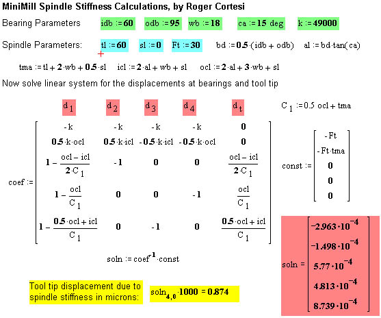
Now we need to check what the bearing spacing should be. From the error budget we know that the maximum deflection of the tool tip due to compliance in the spindle bearings is 0.86 mm (0.000034 inches). To calculate the stiffness the following model was setup
|
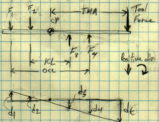
| Figure 2: A sketch showing the geometric variables needed to calculate the spindle stiffness. |
|
| Figure 3: A sketch showing the force and moment balance variables, and the displacements to calculate the spindle stiffness. |
|
| Figure 4: A screen dump from the MathCAD worksheet for the spindle stiffness calculations. The bearing variables (dimensions, odb, idb, wb [mm]; contact angle, ca [deg]; and stiffness, k [N/mm] are in green. The spindle parameters (tool tip to bearing face, tl [mm]; spacer distance, sl [mm]; and tool tip force, Ft [N]) are in teal. The unknown displacements ( d1, d2, d3, d4, dt [mm]) are in pink, and solved by the system of equations described by matrices "coef" and "const". The final result, tool tip displacement in [mm] appears in yellow. The values entered above are for the RHP/NSK T7012CTSU bearing. The tool tip displacement in this case is just above (0.01 mm) the value specified by the error budget. |
The spindle housing is maintained at positive pressure to blow chips and dirt away from the bearings.
 |
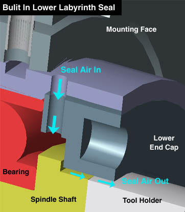 |
| Figure 5: The air path in the lower labyrinth seal, to prevent chips and dirt from contaminating the bearings. | |
We considered both an air cooled and water cooled spindle options. An air cooled spindle would offer the advantage of requiring a water source and pumping equipment. After running doing the heat transfer calculations it was determined that air cooling might be able to maintain the desired spindle temperature (especially for a spindle in the 2 kW range). However, given the limited time allotted for the development of the spindle. We choose the water cooled design because is it is much more robust in controlling the temperature of the housing.
The cooling water is obtained from a faucet and discharged to the drain. The flow is controlled by a temperature controlled valve. When the temperature exceeds a preset value a valve is open and the cooling water flows to the spindle. We estimate that if the spindle is dissipating 200 W of heat (10% of a 2 kW Spindle motor) it will take about 3 gallons per hour to hold the spindle at within 2 C of air temperature (assuming the cooling water enters at a temperature of 10 C). This is a conservatively high estimate because it assumes that our spindle is running at full power all the time. We can glue a thermo sensor to the housing near the mounting bearings.
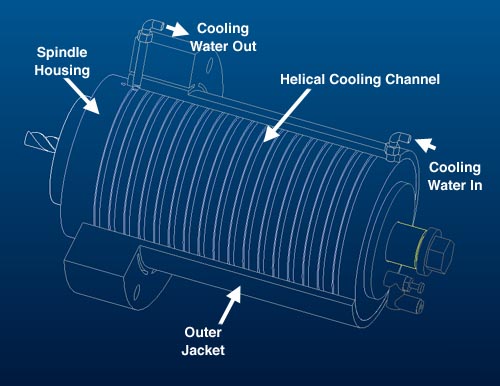
A helical groove is 2 mm wide and 2 mm deep is cut into the inner housing and used as a channel for the water to flow through. The bearing section of the spindle (at the mounting flange) is the area where temperature control is most important. This is were the temperature sensor would be mounted. The cooling water enters from the opposite end (the motor end), to that it is warmed up before entering the section of groove next to the bearings. Otherwise the cold water would cause the housing to contract local around the bearing and that would be bad. A cheep plastic check valve could be place in the line to prevent the water from accidentally being pumped in the wrong directions and destroying the bearings.
|
| Figure 6: The helical cooling channel between the housing and the outer jacket. |
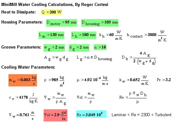
The figures below are screen dumps from the MathCAD file used to calculate the parameters for spindle cooling. These calculations make several assumptions:
|
| Figure 7: The first step in the cooling calculations. The Power to be dissipated is entered (yellow) along with the geometric parameters of the spindle housing and groove (green). The mass flow rate is also enters (orange). The thermal properties of the housing material (in this case Aluminum) and the cooling water are entered. The velocity, volume flow rate (pink) and Reynolds Number (blue) are calculated for the cooling water in the groove. |
|
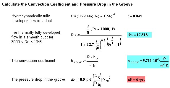
| Figure 8: Next calculate the convection coefficient (between the water and groove wall), and the pressure loss in the water stream in the pipe. Equations are from Mills Basic Heat and Mass Transfer. These calculations assume fully developed flow (hydrodynamically and thermally). This assumption is validated by checking the hydrodynamic and thermal entry lengths against the groove length. For this configuration we see that these are about 5% of the total length, so the assumption is valid. |
|
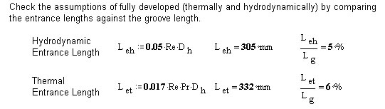
| Figure 9: The thermal resistances for each of the elements in our thermal circuit is calculated. |
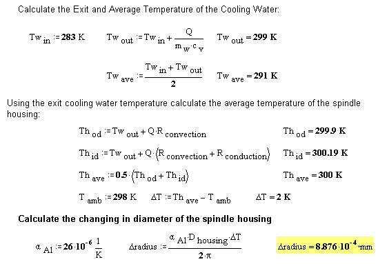
|
| Figure 10: The cooling water temperature and housing temperatures are calculated. We assume that the cooling water enters the machine at 10 degrees C (283 K). The exit temperature is calculated. Since the bearings are held at the end of the spindle which the water exits, we use the water exit temperature (Two) for the water temperature in the groove. |
For the prototype and the initial/ultra low cost versions of the mini-mill we using a manual tool change mechanism. This is accomplished by means of a Number 30 Taper and a draw bolt running up the length of the spindle shaft. The tool draw bolt is tensioned by a number of disk springs. The No. 30 Taper is readily available standard and easy to implement.
For a Mini-Mill that will be used in a production environment automatic tool changing is a necessity. This requires the addition of a power draw bar mechanism to clamp and release the tool holder. However, we have looked and several manufactures of power draw bars, and we will attempt to size the main spindle shaft to all the addition of these by changing simply the interior profile of the spindle shaft.