Back to Roger's Design Portfolio
The MesoMill
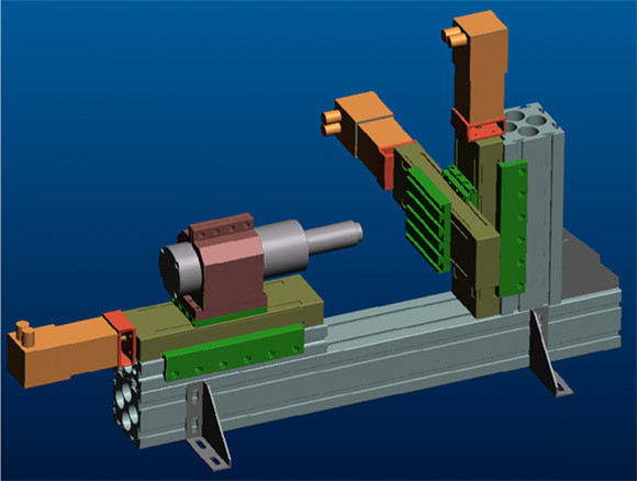
Pro/Engineer Model of the MesoMill.
Goal
The goal of the MesoMill is quickly build a small desktop milling machine.
MesoMill Design Observations
- The spindle is likely to be the heaviest single component in the machine, so DON’T fight gravity, make the machine horizontal.
- Because of the small tool sizes used, the compliance in the tool will be much larger than the compliance in the machine.
- Because of the two conditions above, the predominate errors will not be from structural deflection. They will be from alignment and accuracy of the linear motion elements. So MINIMIZE the number of interfaces when connecting components.
Overview Sketch
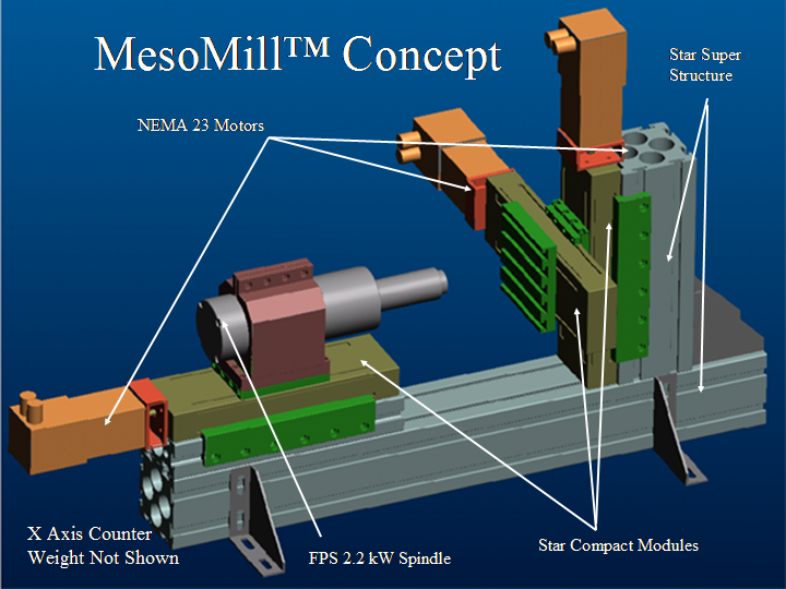
An overview of the MesoMill showing the major components.
The Z axis has the spindle. The Y axis is verticle. The X-axis is horizontal. The couterweight to ballence out the x-axis motor is not shown in the above image.
Components
- This machine is the extreme of building a machine from off the shelf components
- Star Linear™ makes modular structural elements that are used for the machine’s structure
- Star Linear™ makes a wide range of linear motion components which can be used to move the axis of the machine.
MesoMill Features
- 120 mm (5 in) work cube
- Overall Dimensions of 750 x 400 x 300 mm
- All Compact Motion Modules are the same for cost savings
- Minimal custom parts needed
Required Custom Parts
Listed below are the custom parts required to assemble the MesoMill.
|
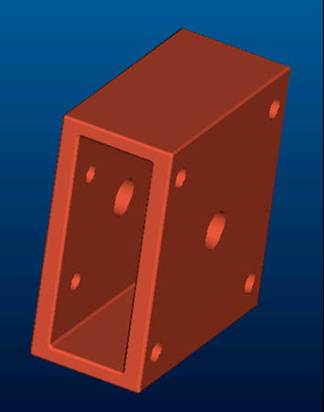
Motor mount to connect Motors to linear motion components (3 required).
|
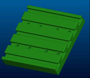
Work Table (1 required).
|
|
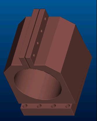
Spindle Mounting Bracket (1 required).
|
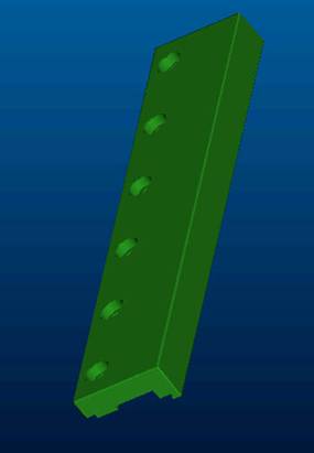
Module Attachment Fixure. This is used to attach the different modles together (4 Required). The machine could be built with out these, but they make it more compact, thereby reducing alignment errors.
|
Motion Module Mounting Concepts
There are two concepts for mounting the motion modules from Star Linear to the structural members.
Mounting with Stock Parts
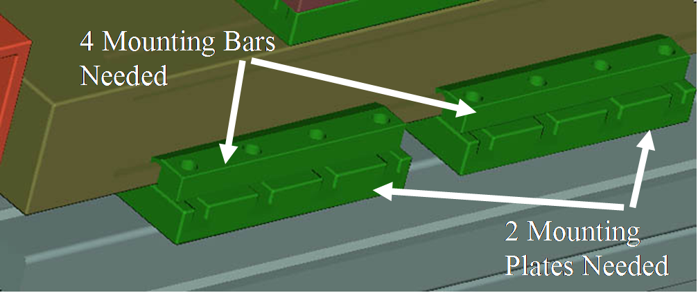
Mounting the motion module with stock parts from Star Linear.
- 2 Degrees of Freedom Elastically Constrained
- Interface Errors due to 8 surface interfaces
- 32 Fasteners Needed
- Alignment dependant on initial alignment of the machine
Mounting with Custom Parts
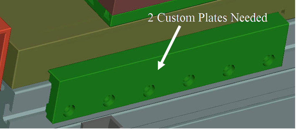
Mounting the motion module with custom parts.
- 5 Degrees of Freedom Elastically Constrained
- Interface Errors due to 3 surface interfaces
- 12 Fasteners Needed
- Alignment Dependent on Custom Plate
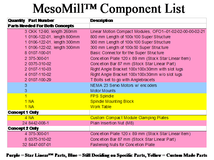
MesoMill Component List
Estimation of MesoMill Alignment Errors
Most of the errors in the MesoMill will be due to misalignment of the components.
- The very rough estimate for the errors due to the
roll pitch and yaw of the carriages is about 30 microns.
- If the L structure is perpendicular to 5 arc seconds
this will add about another 10 microns of error
at the tool tip.
- Still need data on the super structure straightness...
- Still need data on the actual roll pitch and yaw of
the carriages.
- The big question is are these alignment errors repeatable?
If so they can be corrected by the controller.
MesoMill Market
- Rapid Prototyping
- In "field" work (shipboard, oil crews, etc.)
- Education
- the 5 inch work volume and 75 micron accuracy goal are consistent with most university needs.
- Can be sold in "kit" form
- How about a multi university contest on who can build the most accurate machine using the "kit."
- Can be used to teach all sorts of mechanical, electricalm and controls engineering.
- Could this be the hardware element that makes the international design contest truly international? By allowing cross national teams to work on concepts and idea apart and then come together?
- A standard for CNC controller companies to compare their equipment on.
Motor and Controller
- The MesoMill™ currently has a NEMA 23 motors with a custom motor mount to save a little space.
- These could be replaced by the motors out of the Compact Module™ catalog to allow building to go even faster.
- We still need to select a controler.
Copyright: Roger Cortesi 1999-2006


