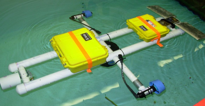
AUV mockup in tow tank for drag testing.
AUV mockup in tow tank for drag testing.
Tow Tank Testing Movie (Quicktime 5 MB)
AUV Configuration
and Programming Guide (PDF 150 KB).
Work in Progress
Being the faculty representative for a project like this is tricky. You want the students to do as much of the work as they can and at the same time you want to steer them away from the really bad ideas. Additionally, in a project as complicated as this, there will be some aspects which are just too hard for the students to do in the time they have allotted for the project.
This club was formed with the intention of building a vehicle to compete in AUVSI's Student AUV Contest.
Before the student's got involved, the other faculty representative and I felt it necessary to select and become familiar with most of the major components for the vehicle. This allowed us to provide some good instruction for the students on interfacing with the hardware. We selected the following components:
One of the first steps that we helped the students work through was determining the functional requirements (FR) of the vehicle. These FR's were determined from two sources: the rules of the AUVSI Contest and other envisioned uses for the vehicle.
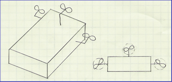
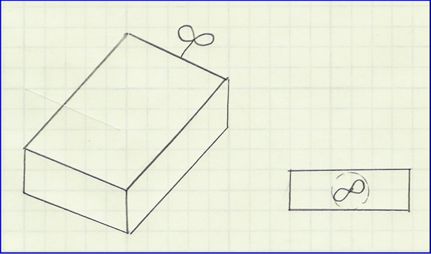
We had the students think of many different ways that thrusters and control surfaces could be arranged to maneuver a vehicle in three dimensions. Here is an example of three configuration considered.
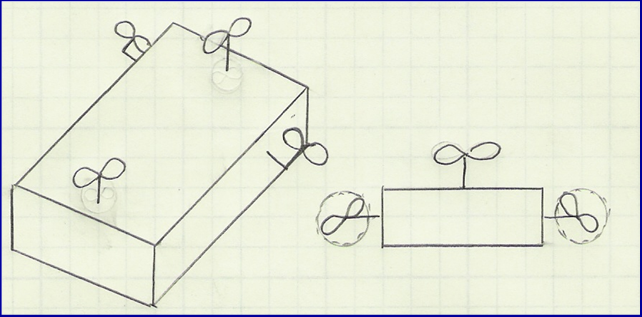
Port and starboard main propulsion thrusters. Fore and aft vertical
thrusters for depth and pitch control.
This configuration is one of the more common configurations seen at the AUVSI competition. The only direction this vehicle cannot travel is sideways.
| Advantages | Disadvantages |
|---|---|
|
|
Three main propulsion thrusters arranged in a triangle (when viewed from
stern).
This design uses only three thrusters, thereby saving weight and money. All three thrusters are main propulsion thrusters. By operating the thrusters in a coordinated fashion they can control both pitch and yaw. Stationary depth holding is more difficult. All the thrusters can be used for forward propulsion, so this is a more efficient use of thruster mass. By comparison, configuration 1 only uses 50% of its thruster mass for forward propulsion.
| Advantages | Disadvantages |
|---|---|
|
|
This configuration uses a single main thruster for propulsion. Control
surfaces are used for pitch and heading control.
This configuration only uses a single main thruster for propulsion. Pitch and heading are controlled by control surfaces.
| Advantages | Disadvantages |
|---|---|
|
|
Many other thruster configurations were considered. Including:
Here is a configuration that I came up with. It uses 8 bilge pump to allow an AUV to travel: forwards, backwards, pitch up/down, yaw left/right, slide sideways, and move vertically. The piping is arranged such that the pump suctions aid the direction of intended movement in most cases. Too bad bilge pumps are a very inconsistent source of thrust.
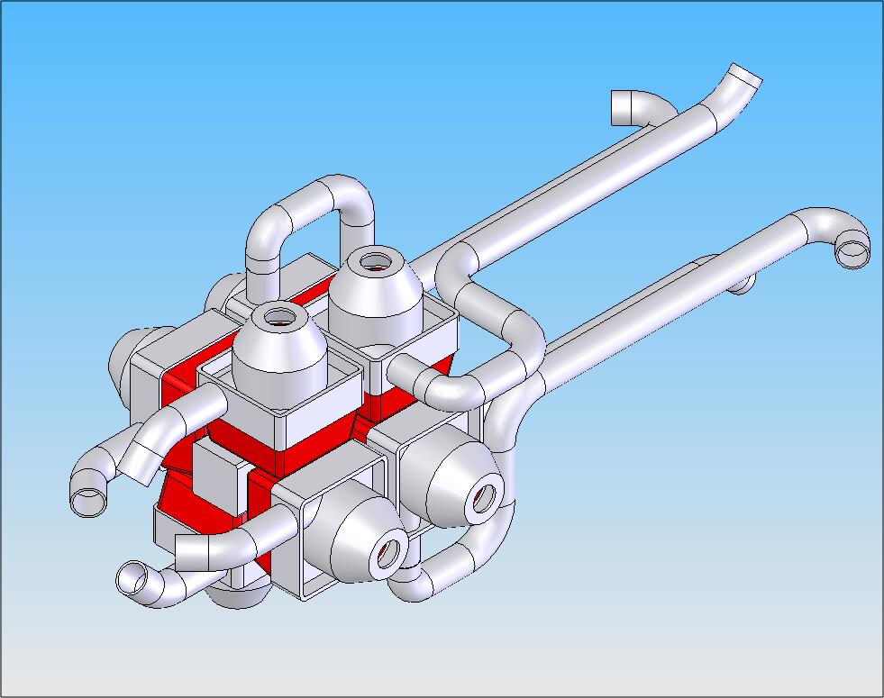
A Solid Works sketch model I made of my bilge pump maneuvering unit.
Figuring out which pumps should run to move the vehicle in each of the above mentioned directions is left as an exercise for the reader.
Then I took the students through the exercise of selecting criterion for comparing each concept. Below are the results from one round of comparisons.
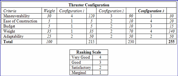
The rankings for configurations 1, 2, and 3. This round of comparisons
indicate that configuration 3 is preferable to configurations 1 or 2. See
the text for why we chose to NOT use configuration 3.
The above figure shows a set of comparisons which the students made. This comparisons indicate that configuration 3 is preferable to configurations 1 or 2. There we a couple of problems with this comparison.
The final configuration for the first version of the vehicle.
The final thruster configuration for the first version of the vehicle is not one of the configurations listed above. In an attempt to save weight we decided to use a port and starboard main thruster and control surfaces to control depth. Personnel usage was another factor in deciding to try to build a set of control surfaces. During the semester there were 12 students working on the project. Designing and building the control surfaces and their actuators in a waterproof housing was a full time project for three of them.
The control surface project was a chance for those students to take a project from the initial concept to the final detailed design through to the construction. This was a fantastic learning experience which is the point of the exercise of course.
As it turns out, building a waterproof box that is lighter than a pair of small commercially available thrusters is harder than they thought. It is likely that the control surfaces will be replaced with a pair of thrusters for depth control.
The table below lists the components we wanted the CPU to interface with:
| Equipment | Number of Interfaces | |||||
|---|---|---|---|---|---|---|
| Serial | A/D | D/A | GIO | USB | Ethernet | |
| Radio Modem | 1 | |||||
| Tethered Comms Link | 1* | 1* | ||||
| 4 Thrusters | 4 | 4 | ||||
| Depth Sensor | 1 | |||||
| Compass | 1 | |||||
| DVL or IMU | 1 | |||||
| 2 Cameras | 2* | 2* | ||||
| Marker Release Mech | 1* | 1* | ||||
| Total | 3-6 | 5 | 4-5 | 0-1 | 0-2 | 0-1 |
A number of factors went into selecting the CPU for the vehicle. These included:
| Advantages | Disadvantages | |
|---|---|---|
|
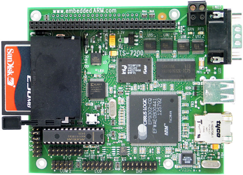
Technologic Systems, TS-7200 ARM Based PC104 SBC
|
|
|
|
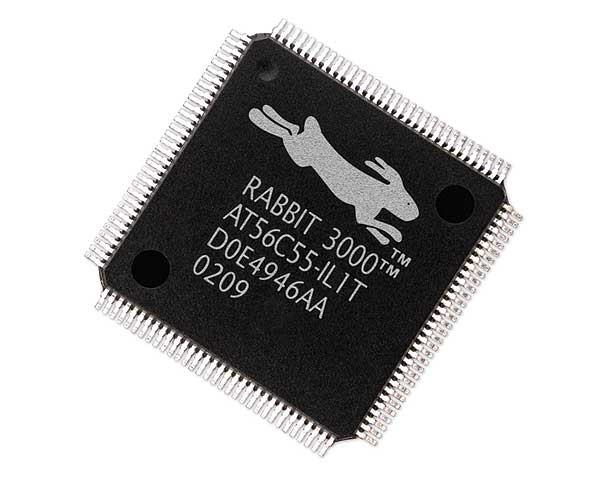
Rabbit 3000 Microprocessor
|
|
|
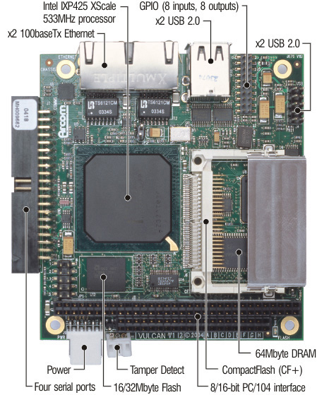
| Pentium Based PC104 SBC
Arcom
and Parvus
are two big manufactures of single board computers.
|
|
|
*Running the computer from onboard flash drastically speeds up boot times (less than 5 seconds) and provides a journaling file system (which handles inadvertent loss of power much more gracefully). But the gcc compiler and development environment will not fit on the onboard flash so compiling must be done off the board.
I selected Technologic Systems TS-7200 for the AUV CPU. I continue to be very impressed by this board. It is an excellent choice for projects like this.
"Lets just get a piece of PVC pipe and make the hull out of that!"
Anyone who has every tried to build an AUV for the first time
The only benefit of the PVC pipe hull is hydrodynamic.
Here are the problems with a PVC pipe hull:
The above reasons are why I selected Pelican Cases to provide the waterproof enclosures for the vehicle. They provide:
I have started writing an AUV Programming Guide (PDF). Currently, it covers the initial configuration of our ARM based single board computer. This too is a work in progress.
We decided to try to build control surfaces to control the vehicle's pitch and depth. For this to be worth while the control surfaces and their actuators should weigh less than a pair of thrusters. Otherwise it is simpler to just use a pair of thrusters for depth control. Additionally, this was undertaken to give three of the students a small self contained project which would take them all the way through the design process.
"Its a waterproof box with a motor inside and shaft coming out.
How hard can that be?"
A student to remain unnamed
The basic vision was a waterproof box with the shaft for the control surfaces coming out either side. This "servo box" could then be mounted on the AUV's frame in the desired location.
Different types of actuators were considered, including stepper motors and hobby servos. The students selected hobby servos as we already had circuit cards to control them via serial commands.
Once servos were selected, the students considered several mechanisms to connect the servo to the shaft. These included linkages, gears and hydraulic rams. The students elected to use a linkage.
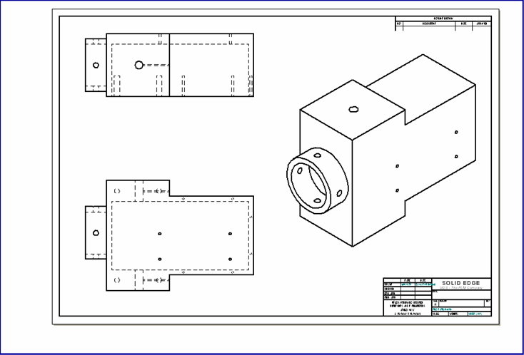
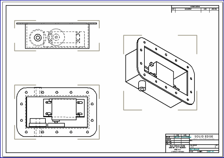
An early sketch model of the servo box.
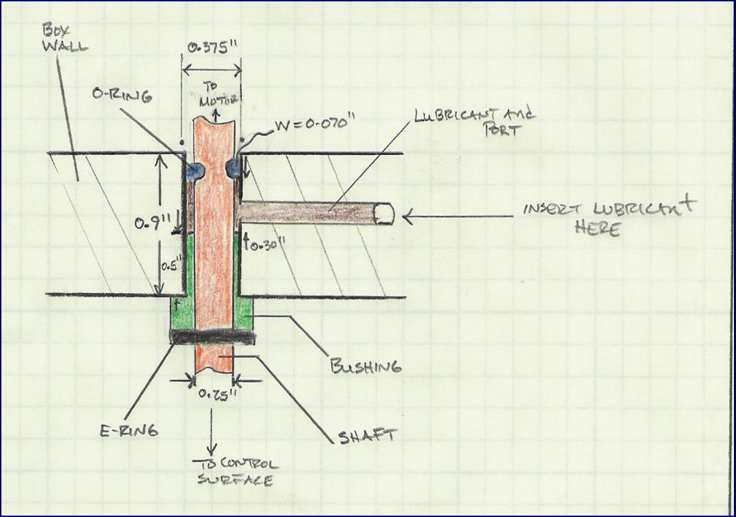
An early sketch of the proposed shaft seals.
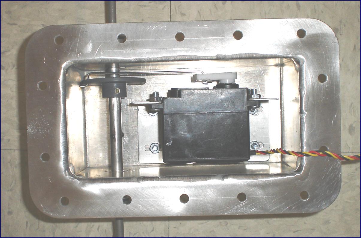
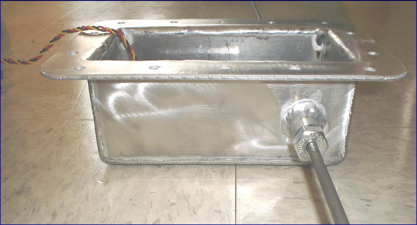
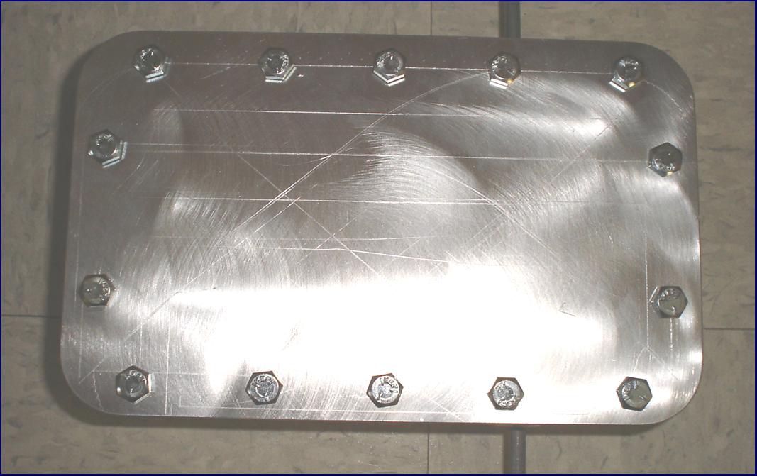
The final servo box was a folded and welded sheet metal box. The shaft seals were tapered cones and o-rings. The there was a lot of wasted space in the box. Therefore, weight had to be added to the vehicle to make it neutrally buoyant. This causes the servo box to weigh much more than two thrusters. Additionally the linkage connecting the servo to the shaft is too flimsy.
Here are some photos of the final servo box for the control surfaces:
|
|
|
|
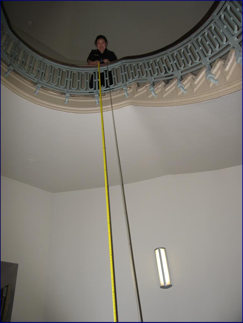
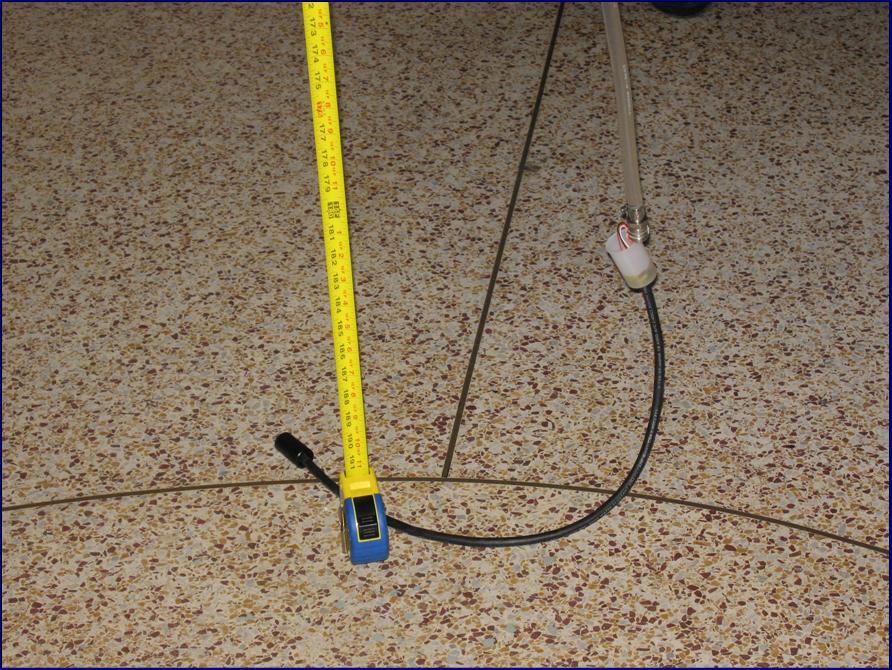
Initially the students tried to use a depth cell from the past vehicle. This cell required an external bridge circuit and regulated power supply. Additionally, since the cell was designed to be mounted in a pipe the end with the wires was not waterproof. So it had to be potted in epoxy, since the depth cell on our vehicle would be mounted on the frame with an external cable running back to the CPU housing. Calibrating the bridge circuit also required making a 30 foot water column.
|
|
Calibrating the old depth cell.
This old depth cell was replaced by a fully waterproof cell which can take 13-28 VDC, and provide a linear 0-10 VDC proportional to 0-30 feet of depth in a single compact package requiring no external circuitry.
The new completely self contained depth cell