Design Sections:
| Pictures and Diagrams:
Design Sections: |
|
The Class & Contest
During the spring semester of my sophomore year at MIT I took 2.007, Design and Manufacturing I. This class uses the 2.70 contest as a vehicle to teach basic design skill. If you are not familiar with the class or the contest please go to the home page for the class and the contest rules for 1997.
I'm assuming that you are familiar with the 1997 contest. In short, your machine had to get as much stuff (read as hockey pucks, balls, and your machine) from your side of the table to your opponents in 30 seconds. You opponent is try to do same against you.
My Machine Overview
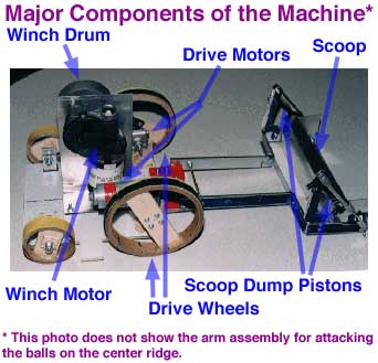
My overall design strategy was to first try to sweep the balls off the center ridge, and then to scoop as many puck to my opponent's side as possible.
I divided the problem into three basic parts and designed and build a module for each. The driving module is what (obviously) moves the machine around the table, the scoop module is was allows my machine to pickup and dump hockey pucks, and balls over the center ridge or the side-walls of the table. The third module is the CRAM, Center Ridge Attack Module, (cool acronym yes?) it is used to knock the balls on the center ridge onto my opponent's side of the table.
Designing the Drive Module
Key Features:
- Botch Motors, powerful and easy to use
- Large Drive Wheels, speed
- Front Wheel Drive, maneuverability
The drive module was the most straight forward to design and build. The two Botch motors in the kit were used because of their power and ease of mounting. The only other motor pair issued was the two Ford windshield-wiper motors. The Ford motors were rule of because they were very heavy and more importantly, they provide different amounts of torque depending on which direction they spin. It is very difficult to position the Ford motors to have there shafts on opposite side of the machine with the same torque in the same direction.
The drive wheels in an earlier model were the same size as the rear wheels (see the photo of the sketch model an you will notice that all for wheels are the same size). I switched to larger drive wheels to make my machine faster. It is important to clear the center ridge quickly. If I went against a machine that drove faster then mine, I would not be able to beat them down the length of the ridge and they would knock the balls onto my side of the table. The original design called for the smaller wheels because for my machine to be successful it as to do a lot of reasonably precise maneuvering. I was concerned that the increased speed would make controlling the machine too difficult. The machine could still be controlled at this speed.
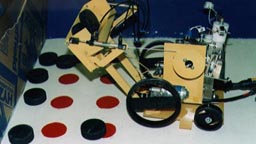
The above photo shows my machine when it was about 1/3 of the way completed. As you can see it is basically just a scoop that can be raised and lowered with the winch (the cable connecting the winch to the scoop is not in the above photo. The CRAM is also not in the photo.
Designing the Scoop Module
Key Features:
- Able to dump 3 hockey pucks over either the center ridge or the side-walls
- Scoop can be used to knock items off the center ridge
- Raising and lowing is very simple.
The scoop module is very simple but it does require a lot of tweaking. The scoop was made from the 1/8" Aluminum sheet metal. A Ford motor is used to drive the winch, which raises and lowers the scoop. Two pneumatic pistons are used to dump the scoop forward. The Scoop module had to be dimensioned with the driving module so that the machine would fit in the required dimensions, and the scoop would still be able to dump objects over the side-walls.
Designing the CRAM
Key Features:
- Reliable trigger mechanism
- Can be mounted quickly and securely on either side of the machine
- Optional arm jettison mode
Problems:
- Arm not long enough
- Arm and mounting plate not stiff enough
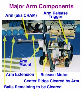
The above photo shows the main part of the arm assembly that is used to clear the balls off the center ridge of the table. This arm assembly is also known as the Center Ridge Attack Module (CRAM). The CRAM was the hardest part of the machine for me to build. It never preformed as flawlessly as it should/could have. There were quite a few design issues when designing and building the CRAM. One of the trickiest to solve was the problem of being able to securely and easily mount the CRAM so that the arm extended off either side of the machine. This was necessary because there was no telling until right before I have drive the machine which side of the center wall I would start on
The biggest problem was the stiffness of the arm. I didn't make the arm stiff enough. Rather then forcefully and definitively sweeping the balls off the center ridge sometime it would just ride up and skim across the tops of the balls and not sweep them off.
It also was not quite long enough. The was because the width of the machine was only 12" and the arm had to fully retract into the machine. At its original length the arm barely reached the balls on the center ridge. So to be able to knock them off required driving the machine in exactly a straight line next to the ridge. That level of precision drive was not possible.
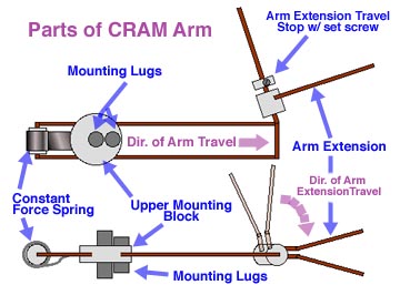
The solution to this was to make the arm longer somehow but still have it fit into the machine. The solution as an extension on the arm that was vertical when the arm was retracted (therefor not taking up any precious horizontal space) and would flop down into the horizontal position when the arm extended (see figure below).
Notice in the above figure that the mounting lugs protrude from both side of the upper mounting block. This allows the arm to be mounted with either side up, depending on which side of the machine it needs to be mounted on. It has to be flipped so that the arm is always pointing forward.
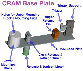
In addition to the arm pictured above the CRAM has a second main part, the CRAM Base Plate. This is what the arm attached to. This plate is easily removed from the machine and rotated 180 degrees so the arm on the other side of the machine.